Gas guide tube assembly, liquid storage device, humidifier, and ventilator

a gas guide tube and tube body technology, applied in the field of respiratory therapy equipment, can solve the problems of degrading the performance of the main unit, water inhalation into the user, damage to the electric elements in the main unit,

Active Publication Date: 2022-02-15
BMC MEDICAL
View PDF17 Cites 0 Cited by
  • Summary
  • Abstract
  • Description
  • Claims
  • Application Information

AI Technical Summary

Benefits of technology

[0028]The gas guide tube assembly provided in the present invention may be disposed in the liquid storage cavity of a humidifier, and the gas outlet port of a gas outlet guiding tube of the gas guide tube assembly communicates with a gas outlet of the liquid storage cavity. Since a guide tube is connected with the gas inlet port of a gas outlet guiding tube of the gas guide tube assembly, the gas is guided via the guide tube to flow into the gas inlet port of the gas outlet guiding tube; in addition, the guide tube has a plurality of gas reflux ports, so that the liquid will flow out via the other gas reflux ports even if the liquid flows in via one gas reflux port incurred by swaying of the liquid storage cavity, and thereby the possibility of liquid flowing into the gas inlet port of the gas outlet guiding tube is decreased. Furthermore, owing to the existence of the gas outlet guiding tube and the guide tube, the flow path of the gas in the liquid storage cavity is lengthened, so that the gas can be mixed extensively with the vapor produced through evaporation, and thereby the outflow gas has expected humidity and temperature.

Problems solved by technology

However, some users need to move the humidifier during use.
In the moving process, the water in the water tank may overflow from the gas outlet or gas inlet of the water tank, and the overflow water may enter into the breathing mask through the transfer tube, resulting in water inhalation into the user; or the overflow water may enter into the main unit of the machine, causing degraded performance of the main unit or even damage of the electric elements in the main unit.

Method used


Image

  • Gas guide tube assembly, liquid storage device, humidifier, and ventilator
  • Gas guide tube assembly, liquid storage device, humidifier, and ventilator
  • Gas guide tube assembly, liquid storage device, humidifier, and ventilator

Examples


Embodiment Construction

[0042]In the following description, many details are provided to facilitate thorough understanding on the present invention. However, those skilled in the art should appreciate that the following description only exemplarily describes some preferred embodiments of the present invention, and the present invention can be implemented without one or more of such details. Besides, to avoid confusion with the present invention, some technical features that are well known in the art are not detailed here.

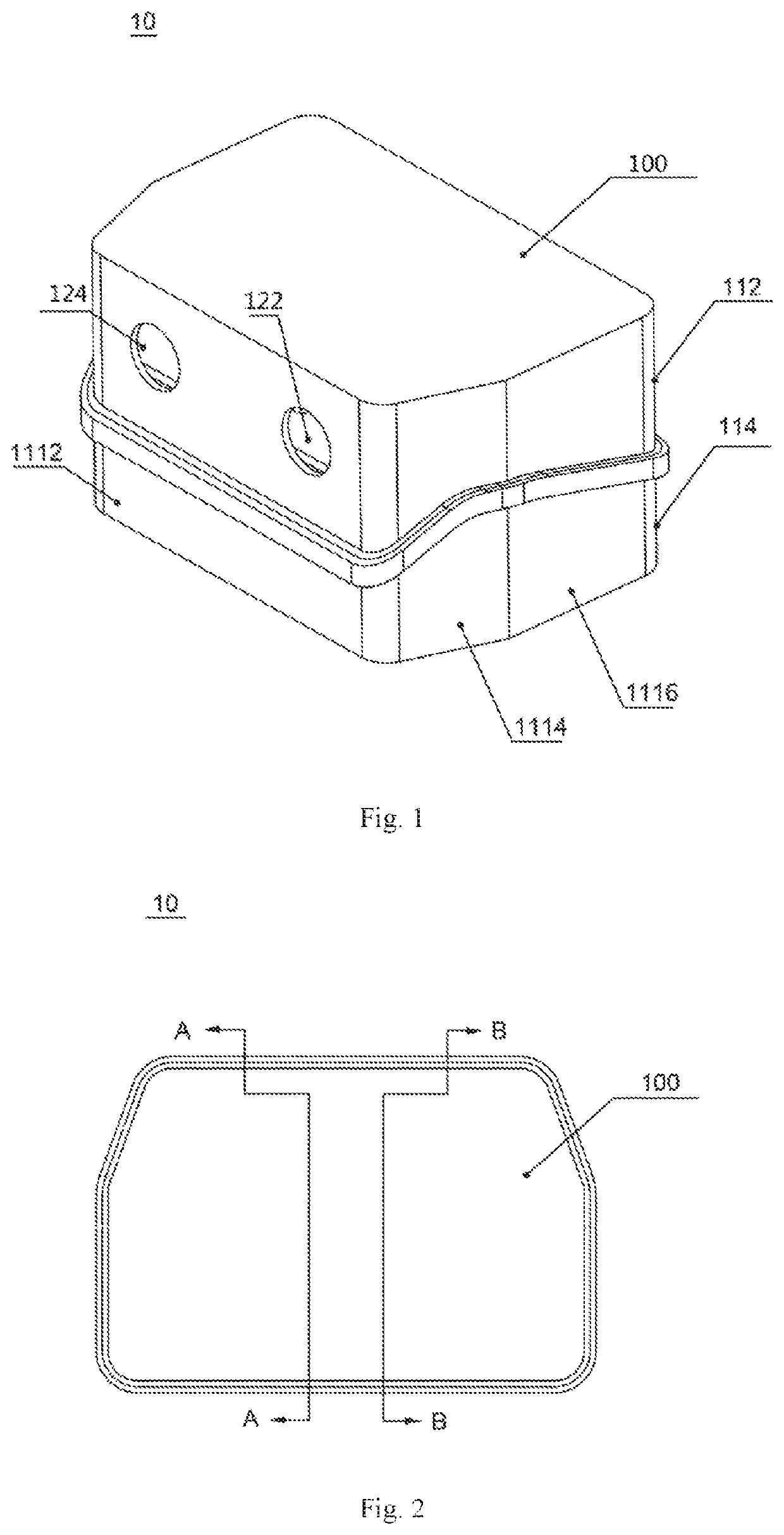
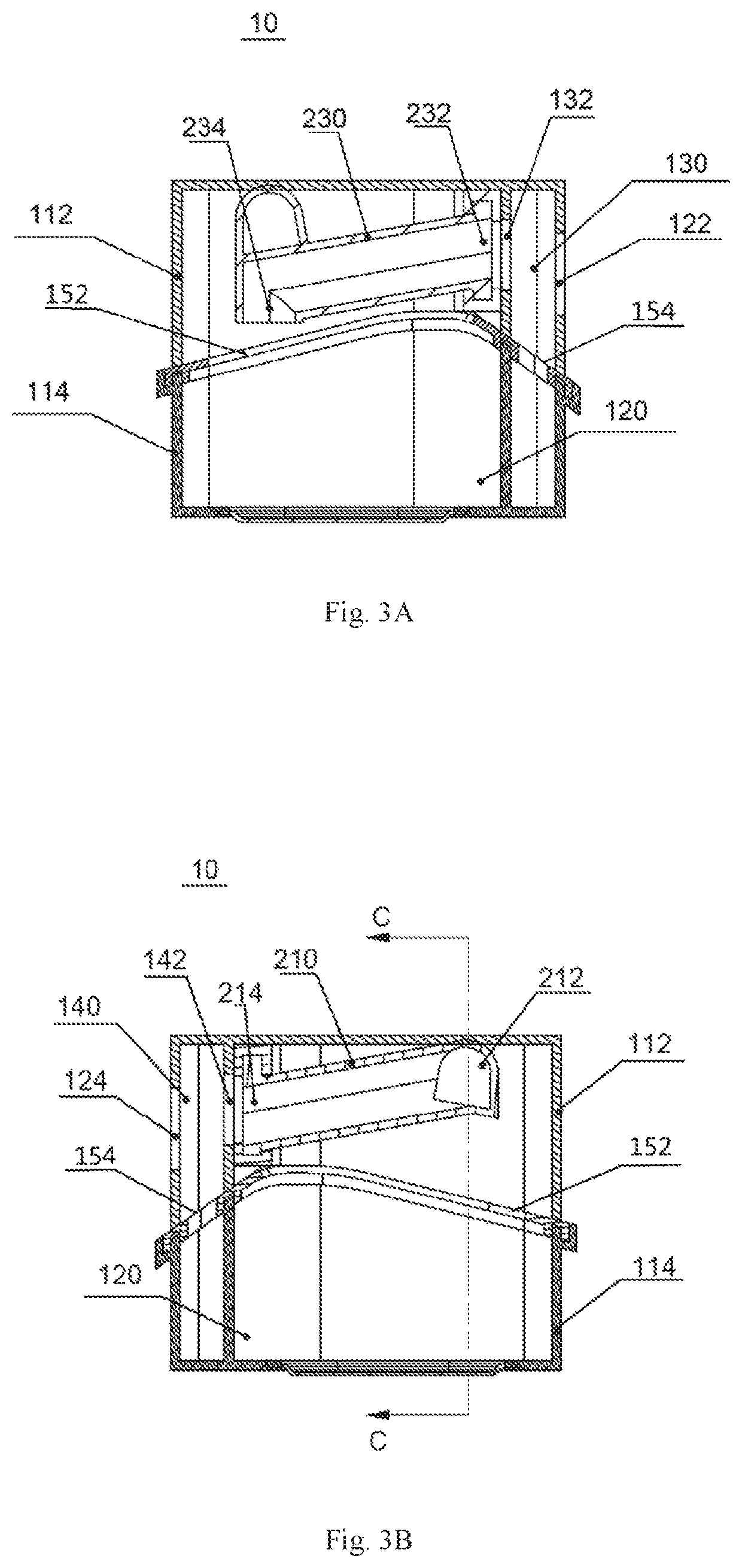
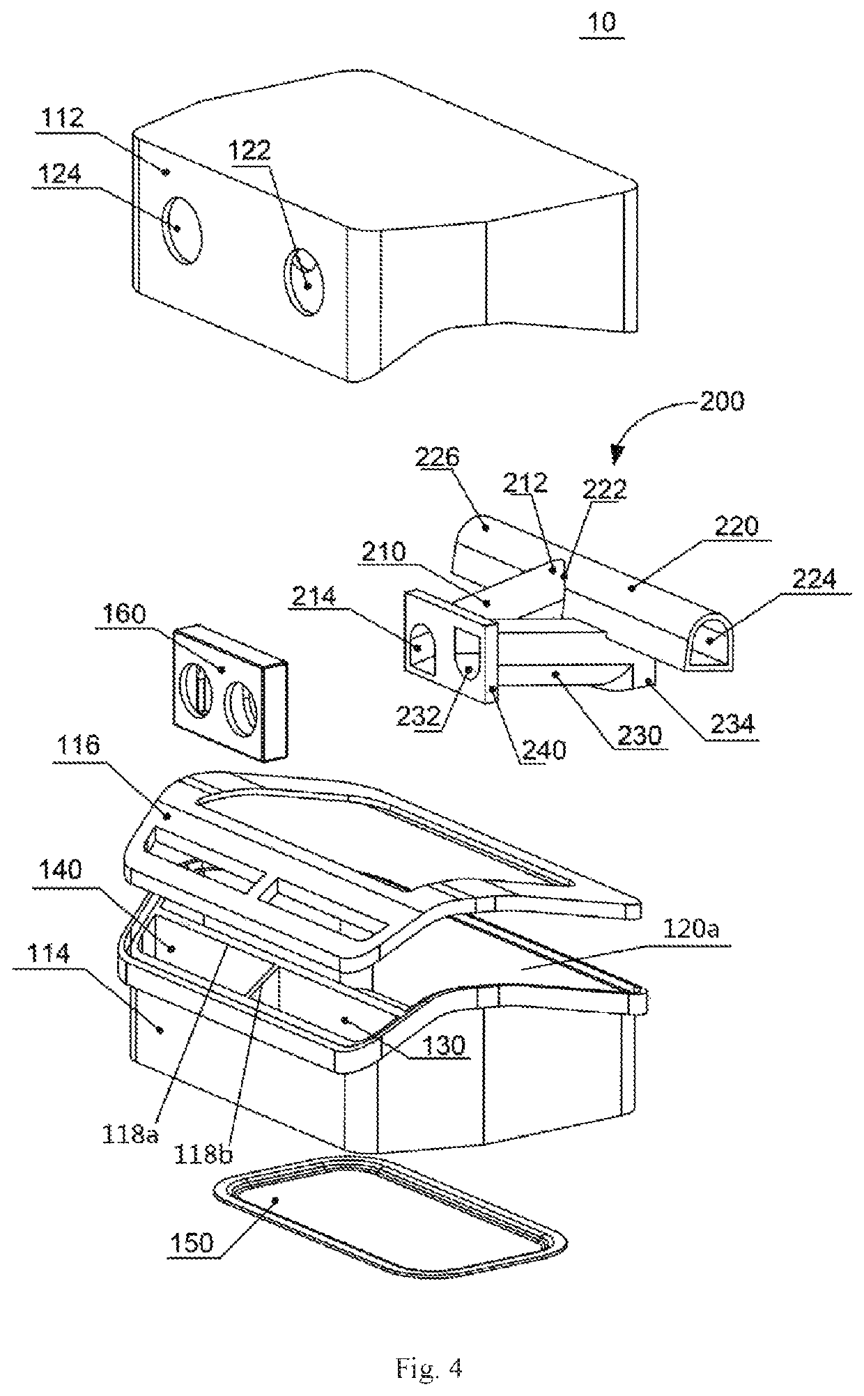
[0043]According to an aspect of the present invention, the present invention provides a gas guide tube assembly for humidifier and a liquid storage device having the gas guide tube assembly. FIGS. 1-9 shows the entire liquid storage device and the components or parts included in the liquid storage device, such as the gas guide tube assembly, upper casing, and lower casing, etc., viewed from different angles. To make the positions and functions of those components or parts in the liquid sto...


PUM


Abstract

A gas guide tube assembly (200), a liquid storage device (10), a humidifier, and a ventilator. The gas guide tube assembly (200) comprises: a gas outlet guiding tube (210) having a gas inlet port (212) and a gas outlet port (214); and a guide tube (220) having a communication port (222) that communicates with the gas inlet port (212) of the gas outlet guiding tube (210) and a plurality of gas reflux ports (224, 226) that communicate with the communication port (222). The gas guide tube assembly (200), when in use, is disposed in a liquid storage cavity (120) of the humidifier, and the gas outlet port (214) of the gas outlet guiding tube (210) of the gas guide tube assembly (200) communicates with a gas outlet (124) of the liquid storage cavity (120). The present invention can solve to a certain extent a problem of water inhalation into the user due to overflow from the gas outlet (124).

Description

CROSS REFERENCE TO RELATED APPLICATIONS[0001]The present application is a National Stage Application, filed under 35 U.S.C. 371, of International Patent Application No. PCT / CN 2017 / 098382, filed on Aug. 22, 2017, which claims for the priority of the Chinese Patent Applications No. 201610782799.3 and No. 201610782796.X, both filed on Aug. 31, 2016, the content of each of which is incorporated here by reference in entirety.FIELD OF THE INVENTION[0002]The present invention relates to the field of respiratory therapy equipment, particularly to a gas guide tube assembly for the humidifier of a ventilator, a liquid storage device having the gas guide tube assembly, a humidifier having the liquid storage device, and a ventilator having the humidifier.BACKGROUND OF THE INVENTION[0003]Presently, continuous positive airway pressure (CPAP) ventilation with a ventilator is the main treatment for sleep apnea syndrome (such as severe snoring) and other diseases. Wherein, a humidifier is an import...

Claims


Application Information

Patent Timeline
Patent Type & Authority Patents(United States)
IPC IPC(8): A61M16/16A61M16/08
CPCA61M16/16A61M16/0875A61M16/00A61M2205/123A61M2206/10
Inventor ZHUANG, ZHI
Owner BMC MEDICAL
Why Eureka
Try Eureka