System, testing assembly and method for fatigue testing a wind turbine blade

a wind turbine and blade technology, applied in the field of system for fatigue testing can solve the problems of small damage, fatigue crack or other failure of wind turbine blades, and modeling limitations

Active Publication Date: 2022-02-22
SIEMENS GAMESA RENEWABLE ENERGY AS
View PDF11 Cites 0 Cited by
  • Summary
  • Abstract
  • Description
  • Claims
  • Application Information

AI Technical Summary

Benefits of technology

[0007]However, there is still a problem to achieve laboratory fatigue distributions being as close as possible to real fatigue distributions. To achieve the desired fatigue distribution during excitation, typically loads are mounted along the blade to shape the moment distribution in flapwise or edgewise testing. However, the desired load placement for flapwise and edgewise testing are not the same. One test setup is used for flap, while another test setup is used for edge. In particular, it is important to fatigue test the wind turbine blade consistently along a sufficient length of the wind turbine blade and up to a target of maximum fatigue, which can be set by regulations, for example. For these reasons, it is not possible to simulate test fatigue cycles in flapwise directions and edgewise directions simultaneously in a single test while still delivering accurate results. The desired fatigue distribution in case of a combined test must be set for both, flapwise directions and edgewise directions, and thus can only be a compromise. For these reasons, a combined test would result in large overtesting. When a wind turbine blade is overtested, parts of the wind turbine blade are fatigue tested above a target of maximum fatigue. In this case, other parts of the wind turbine blade still need testing up to the target of maximum fatigue. However, the wind turbine blade can only be tested as a whole, even when changing the fatigue distribution. Thus, when testing parts of the wind turbine blade up to their target of maximum fatigue, overtested parts of the wind turbine blade will unavoidably be further fatigued above their target of maximum fatigue. Thus, there is a risk that the overtested parts of the wind turbine blade will break. This would make the fatigue test unsafe to perform and unexploitable for determining whether or not the wind turbine blade can be fatigue tested up to the target of maximum fatigue. However, running separate fatigue tests in the flapwise directions and the edgewise directions to avoid this problem is time consuming and expensive. However, even in separate fatigue tests in the flapwise or edgewise directions, some parts of the wind turbine blade will be overtested because it is not physically possible to achieve the target of maximum fatigue of all parts of the wind turbine blade at the same time. Some parts typically reach the target of maximum fatigue quickly and some targets take many more cycles to reach the target of maximum fatigue. Hence, there is a need for a wind turbine blade testing system that is less expensive to operate and requires less testing time to complete while still providing accurate fatigue testing results and prevents overtesting as much as possible.

Problems solved by technology

That is because every revolution of the wind turbine blades subjects the wind turbine blades to a fatigue cycle, with each of these fatigue cycles causing small amounts of damage.
These damages eventually may lead to a fatigue crack or other failure of the wind turbine blades.
However, modeling has its limitations, including inaccuracies between the model and the manufactured wind turbine blade and the difficulty of accurately modeling operational conditions with varying and randomly occurring loads.
However, there is still a problem to achieve laboratory fatigue distributions being as close as possible to real fatigue distributions.
However, the desired load placement for flapwise and edgewise testing are not the same.
For these reasons, it is not possible to simulate test fatigue cycles in flapwise directions and edgewise directions simultaneously in a single test while still delivering accurate results.
For these reasons, a combined test would result in large overtesting.
However, the wind turbine blade can only be tested as a whole, even when changing the fatigue distribution.
Thus, when testing parts of the wind turbine blade up to their target of maximum fatigue, overtested parts of the wind turbine blade will unavoidably be further fatigued above their target of maximum fatigue.
Thus, there is a risk that the overtested parts of the wind turbine blade will break.
This would make the fatigue test unsafe to perform and unexploitable for determining whether or not the wind turbine blade can be fatigue tested up to the target of maximum fatigue.
However, running separate fatigue tests in the flapwise directions and the edgewise directions to avoid this problem is time consuming and expensive.
However, even in separate fatigue tests in the flapwise or edgewise directions, some parts of the wind turbine blade will be overtested because it is not physically possible to achieve the target of maximum fatigue of all parts of the wind turbine blade at the same time.

Method used


Image

  • System, testing assembly and method for fatigue testing a wind turbine blade
  • System, testing assembly and method for fatigue testing a wind turbine blade
  • System, testing assembly and method for fatigue testing a wind turbine blade

Examples


first embodiment

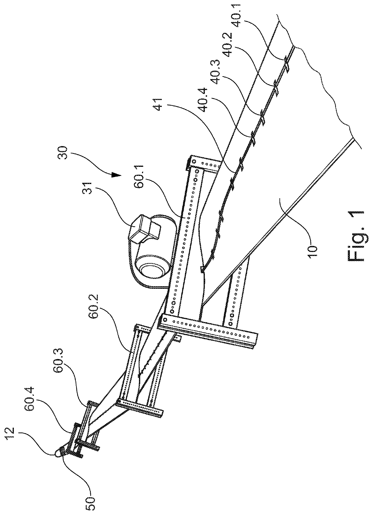
[0030]FIG. 1 shows an embodiment of the testing assembly according to a testing assembly according to embodiments of the invention. The testing assembly comprises a wind turbine blade 10, of which a tip end 12 is shown but part of the wind turbine blade 10 close to a root end 11 as well as a mounting 20, in which the root end 11 is retained, are not shown in this figure. The testing assembly is mounted in the mounting 20 so that it is hanging.

[0031]Four loads 60.1, 60.2, 60.3, and 60.4 are attached to the wind turbine blade 10 spaced apart from each other. The loads 60.1, 60.2, 60.3, and 60.4 are designed as yokes in this embodiment. In particular, each of the yokes comprises four bars attached to one another to form a rectangular shape. Two holding plates are arranged in between the four bars. The holding plates are at one of their sides designed corresponding to the shape of the wind turbine blade 10 at the position of attachment of the yokes to the wind turbine blade 10. The load...

second embodiment

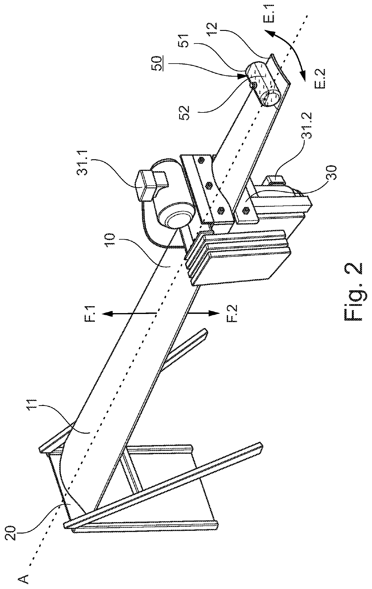
[0035]FIG. 2 shows an embodiment of the testing assembly according to a testing assembly according to embodiments of the invention. This testing assembly with a relatively short wind turbine blade 10 of 5 meters length has been used for evaluating tuning parameters of the tuned liquid damper 50. For illustration purposes only, the measurement devices 40 and wire 41 have been omitted in FIG. 2.

[0036]The root end 11 of the wind turbine blade 10 being retained in the mounting 20 is shown in FIG. 2. Moreover, the longitudinal axis A of the wind turbine blade 10 is shown. Also, flapwise directions F.1 and F.2 and edgewise directions E.1 and E.2 of the wind turbine blade 10 are shown, into which the wind turbine blade 10 is moved, when the actuator assembly 30 with both its actuators 31.1 and 31.2 are being operated. Actuator 31.1 is arranged in the edgewise directions E.1 and E.2 and actuator 31.2 is arranged in the flapwise directions F.1 and F.2. Thereby, when operating the actuator 31...


PUM


Abstract

Provided is a system for fatigue testing a wind turbine blade including: a mounting for retaining a root end of the wind turbine blade, at least one actuator assembly for attachment to the wind turbine blade, the at least one actuator assembly including at least one actuator for exciting the wind turbine blade in flapwise directions and / or edgewise directions, and at least one measuring device for measuring of a stress, a strain and / or a deflection of the wind turbine blade. The system further includes at least one tuned liquid damper for attachment to the wind turbine blade, the tuned liquid damper comprising a container and a liquid contained therein.

Description

CROSS-REFERENCE TO RELATED APPLICATIONS[0001]This application claims priority to EP Application No. 19150096.6, having a filing date of Jan. 2, 2019, the entire contents of which are hereby incorporated by reference.FIELD OF TECHNOLOGY[0002]The following is directed to a system for fatigue testing a wind turbine blade comprising: (a) a mounting for retaining a root end of the wind turbine blade, (b) at least one actuator assembly for attachment to the wind turbine blade, the at least one actuator assembly comprising at least one actuator for exciting the wind turbine blade in flapwise directions and / or edgewise directions, and (c) at least one measuring device for measuring of a stress, a strain and / or a deflection of the wind turbine blade. Moreover, embodiments of the present invention are directed to a testing assembly comprising the system according to embodiments of the invention and the wind turbine blade. Furthermore, embodiments of the present invention are directed to a met...

Claims


Application Information

Patent Timeline
Patent Type & Authority Patents(United States)
IPC IPC(8): G01M5/00
CPCG01M5/005G01M5/0016G01N3/32G01M13/00F03D17/00F05B2260/83
Inventor CHRISTIANSEN, SOEREN
Owner SIEMENS GAMESA RENEWABLE ENERGY AS
Why Eureka
Try Eureka