Route candidate setting system and route candidate setting method

a technology of setting system and setting method, applied in the direction of scene recognition, instruments, navigation instruments, etc., can solve the problem of properly small computing load in providing the second curved line, and achieve the effect of reducing computing load

Active Publication Date: 2022-03-01
MAZDA MOTOR CORP
View PDF15 Cites 0 Cited by
  • Summary
  • Abstract
  • Description
  • Claims
  • Application Information

AI Technical Summary

Benefits of technology

[0005]The present invention has been devised in view of the above-described matter, and an object of the present invention is to provide a route candidate setting system and a route candidate setting method which can properly reduce the computing load, setting the various route candidates.
[0007]According to the present invention, the computing device sets the first curved line as the route candidate for a close range which is positioned relatively closely to the vehicle and sets the second curved line as the route candidate for a far range which is far from the close range. While the first curved line represented by the first function having the relatively high degree can set the precise route candidate which is capable of meeting many requirements, the computing load in providing the first curved line is large. Meanwhile, the second curved line represented by the second function having the relatively low degree does not cope with many requirements like the first curved line, but the computing load in providing the second curved line is properly small. The computing device can properly reduce the computing load in setting the route candidate by setting the second curved line as part of the route candidate.
[0009]Thus, according to the present invention, in the case where the obstacle is detected by the obstacle information acquisition device, the computing device does not provide the first curved line having the terminal point which corresponds to the grid point located on the forward side, in the advancing direction of the vehicle, of the obstacle and the second curved line having the start point which corresponds to this grid point. Thereby, the route candidate setting system of the present invention can properly reduce the computing load in setting the route candidates, meeting the requirements, such as vehicle's collision avoidance with the obstacle or less discomfort that passengers may feel in operation for this vehicle's collision avoidance.
[0011]The route candidate setting system of this embodiment can more properly reduce the computing load in setting the route candidates, meeting the requirements, such as vehicle's collision avoidance with the obstacle or less discomfort that passengers may feel in operation for this vehicle's collision avoidance.
[0013]According to this embodiment, relational expressions correlated with a yaw angle, a yaw angle speed, and a yaw angle acceleration of the vehicle can be respectively obtained by first-order-third-order differentiations of the quintic function with the x coordinate. The yaw angle, the yaw angle speed, and the yaw angle acceleration of the vehicle can be evaluated by these relational expressions. Consequently, the route candidate setting system of this embodiment can set the route candidates to reduce the discomfort that passengers may feel, considering behavior of the vehicle in a yaw direction.
[0015]According to this embodiment, relational expressions correlated with the yaw angle and the yaw angle speed of the vehicle can be respectively obtained by first-order and second-order differentiations of the cubic function with the x coordinate. The yaw angle and the yaw angle speed of the vehicle can be evaluated by these relational expressions. Consequently, the route candidate setting system of this embodiment can set the route candidates to reduce the discomfort that passengers may feel, considering the behavior of the vehicle in the yaw direction.

Problems solved by technology

Meanwhile, the second curved line represented by the second function having the relatively low degree does not cope with many requirements like the first curved line, but the computing load in providing the second curved line is properly small.

Method used


Image

  • Route candidate setting system and route candidate setting method
  • Route candidate setting system and route candidate setting method
  • Route candidate setting system and route candidate setting method

Examples


Embodiment Construction

[0023]Hereafter, an embodiment of the present invention will be described referring to the accompanying drawings. In the figures, the same constitutional elements have the same reference characters attached, and duplicate descriptions for those are omitted here.

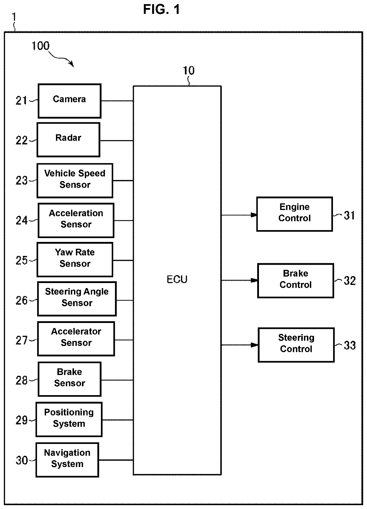
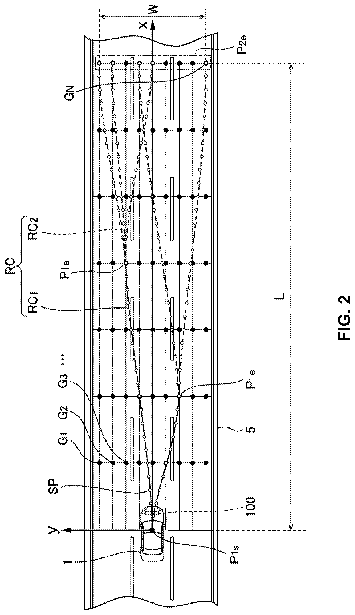
[0024]Referring to FIGS. 1 and 2, an outline of a driving support system 100 as an example of a route candidate setting system according to the present invention will be described. FIG. 1 is a block diagram of the driving support system 100, and FIG. 2 is an explanatory diagram of route candidates RC.

[0025]The driving support system 100 is installed at a vehicle 1 and provides a driving support control to make the vehicle 1 travel along a target route. As shown in FIG. 1, the driving support system 100 comprises an ECU (electric control device) 10, plural sensors, and plural control systems. The plural sensors include a camera 21, a radar 22, and other sensors to detect behavior of the vehicle 1 and driving operations by a pa...


PUM


Abstract

An ECU of a driving support system as a route candidate setting system is configured to provide a first curved line represented by a first function having x coordinate as a variable and y coordinate and a second curved line represented by a second function having x coordinate as a variable and y coordinate and having a lower degree than the first function, and set the first and second curved lines as traveling-route candidate RC. In a case where an obstacle is detected by a camera and a radar, the ECU is configured not to provide the first curved line having its terminal point corresponding to a grid point Gn located on a forward side, in an advancing direction of a vehicle, of the obstacle and the second curved line having its start point corresponding to this grid point Gn.

Description

BACKGROUND OF THE INVENTION[0001]The present invention relates to a route candidate setting system and a route candidate setting method.[0002]An algorithm used for setting candidates of a traveling route of a vehicle (i.e., candidates of a target route for vehicle's actual traveling), such as the potential method, the spline interpolation function, A-star (A*), RRT, or the State Lattice method, is known. A driving support system using this algorithm has been proposed as well.[0003]In the State Lattice method, many grid points are set on a traveling road of the vehicle and candidates of the traveling route of the vehicle are set for these grid points. These route candidates are respectively evaluated in terms of a route cost which relates to an obstacle-avoidance risk and the like. PCT WO 2013 / 051081 (its counterpart US Patent Application Publication No. 2014 / 0244114 A1), for example, discloses a driving support (assistance) system in which plural route candidates are set on a grid m...

Claims


Application Information

Patent Timeline
Patent Type & Authority Patents(United States)
IPC IPC(8): G01C21/34
CPCG01C21/3415G01C21/3602G01C21/3407B60W30/095G08G1/161B60W30/09B60W30/18163G06V20/588G06V20/58
Inventor TAKAHASHI, HIDEKI
Owner MAZDA MOTOR CORP
Why Eureka
Try Eureka