
Inductive absolute position sensor

a position sensor and absolute position technology, applied in the direction of converting sensor output, measuring devices, instruments, etc., can solve the problems of insufficient accuracy, cumbersome above described devices, and insufficient crosstalk between tracks, so as to improve the coupling characteristics, reduce the number of printed circuit winding layers, and improve the effect of implementation

Active Publication Date: 2022-03-01
HEMY8 SA
View PDF5 Cites 0 Cited by
  • Summary
  • Abstract
  • Description
  • Claims
  • Application Information

AI Technical Summary

Benefits of technology

The patent describes a new sensor design that has several advantages over traditional sensors. One advantage is that it only requires two extra components: an improved scale feature pattern and an extra drive winding. This design also reduces unwanted coupling between the drive winding and the sense windings, improoving accuracy. Another advantage is that the sensor allows for separate first and second measuring modes, which helps avoid unwanted coupling between the drive winding. The scale features consist of eddy-current screens or loops that induce current in the sense windings, and they are spatially separated from the drive windings to prevent direct coupling. The sensor also allows for a longer absolute measuring range by using two tracks with half the period of the scale pattern. This reduces the length of each sense windings, which allows for a shorter reading head for the same absolute measuring range.

Problems solved by technology

As mentioned in the specification of the '519 patent, accuracy is limited by crosstalk between tracks, requiring some minimum track separation.
However, multiple scale tracks with a minimum track separation are still required.
Problematically, the above described devices are either be too cumbersome or not accurate enough for use in measuring instruments such as gauging probes, micrometers, dial indicators, etc., mentioned above.

Method used


Image

  • Inductive absolute position sensor
  • Inductive absolute position sensor
  • Inductive absolute position sensor

Examples


Embodiment Construction

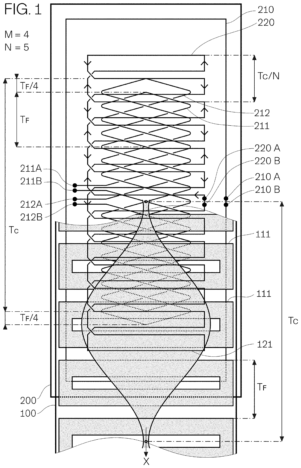
[0031]FIG. 1 shows by way of example an embodiment of the invention manufactured in printed circuit technology, a planar scale 100 being in front of a planar reading head 200 (their substrates shown as transparent for better viewing and explanation). Scale 100 has a first pattern of planar conducting features 111 on its back side or side facing reading head 200 and a second pattern of planar conducting second features 121 on its front side, partially masking first features 111. Reading head's 200 windings on its front layers, closer to the scale, are shown partially hiding windings on its back layers, further from the scale.

[0032]Part of scale 100 in front of reading head 200 is removed for better viewing. For second features 121 to be sufficiently close to the reading head's windings, the scale substrate is thin. Equivalently, a scale may consist of both feature layers on the same side of a substrate thick enough to provide the required stiffness, with both layers behind the substr...


PUM


Abstract

An inductive absolute position sensor has a scale with planar conducting features on a pattern repeating every spatial period TC along a measuring path and a reading head with planar windings: multipolar sine and cosine sense windings of spatial period TF=TC / M, M an integer, a unipolar first drive winding surrounding the sense windings and a multipolar second drive winding of spatial period TC / N along the measuring path, with N=M±1. An electronic circuit makes a first mode measurement using the first drive winding and a second mode measurement using the second drive winding. The absolute position in a range TC is computed from both modes' measurements. The sensor may be as compact as the incremental sensor it replaces, as the scale pattern and second drive winding needed for making it absolute do not need extra space.

Description

TECHNICAL FIELD[0001]The invention relates to inductive absolute position sensors. The inductive absolute position sensors can be used for replacing inductive incremental position sensors in small measuring instruments such as gauging probes, micrometers, dial indicators, etc., with accuracies of micrometers or better within a range of a few centimeters.BACKGROUND[0002]Inductive incremental position sensors usually consist of a reading head with drive and sense windings facing a scale with a periodic pattern of conducting or permeable features influencing the coupling between windings in function of the relative position of scale and reading head, as disclosed in U.S. Pat. No. 4,737,698 to McMullin et al.[0003]Current inductive absolute position sensors are a combination of two or more inductive incremental position sensors of different scale periods. The '698 patent suggests two variants, one combining an incremental sensor of fine period and another of coarse period, the other com...

Claims


Application Information

Patent Timeline
Patent Type & Authority Patents(United States)
IPC IPC(8): G01D5/20
CPCG01D5/2053G01D5/2046G01D5/2497
Inventor MEYER
Owner HEMY8 SA
Learn More