
Techniques for co-siting a metal detector with another detector

a metal detector and cositing technology, applied in the field of cositing metal detectors with other detectors, can solve the problems of two detectors interfering with each other, difficult to operate other sensors on the same head, etc., and achieve the effect of reducing the effect of the coil

Active Publication Date: 2020-02-04
ROKE MANOR RES LTD
View PDF23 Cites 0 Cited by
  • Summary
  • Abstract
  • Description
  • Claims
  • Application Information

AI Technical Summary

Benefits of technology

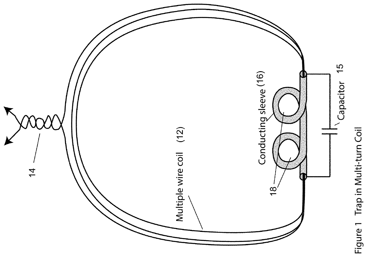
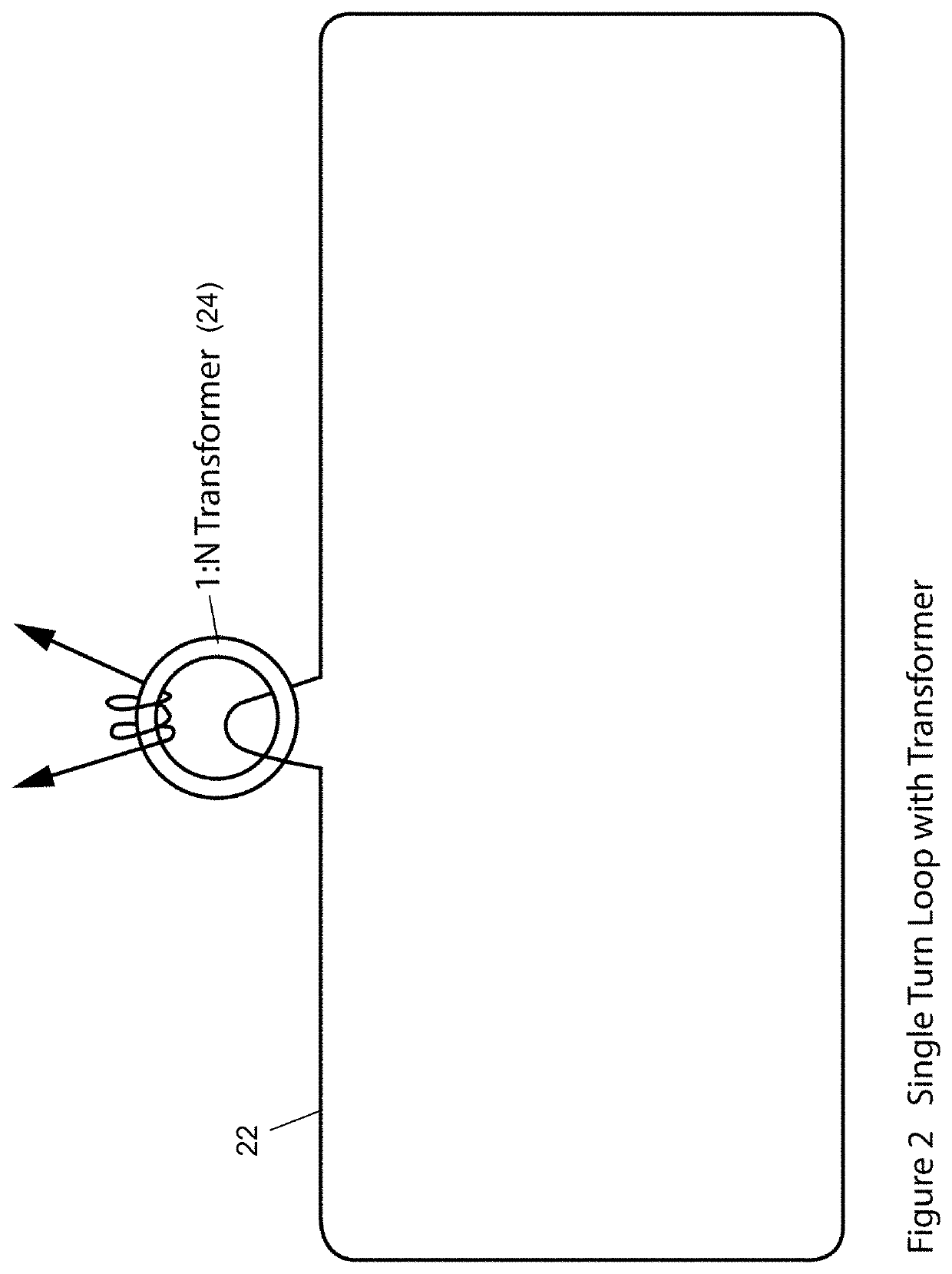
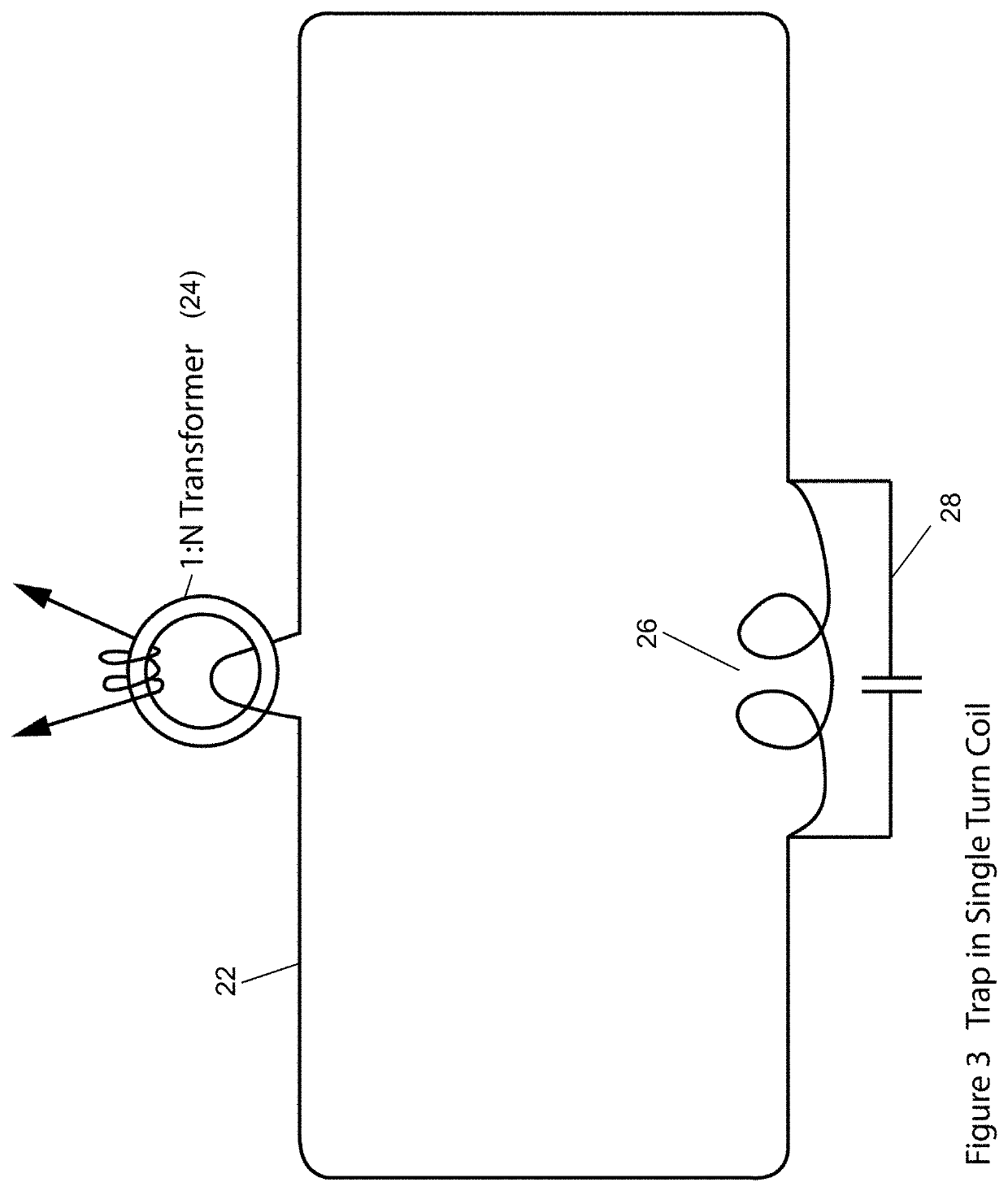
The patent text describes several techniques to place a metal detector coil in proximity to another sensor without affecting its operation. One technique involves using tuned circuits (“traps”) in the metal detector coil to isolate at different frequencies, while another technique involves using a small number of turns or a single turn coil combined with a step up transformer to increase the EMF of the coil. Another technique involves forming the metal detector coil in a plane that follows the sensing field of the other sensor to minimize interference. These techniques help improve the accuracy and reliability of metal detection in various applications.

Problems solved by technology

However, problems can arise with the two detectors interfering with each other.
This represents a large mass and area of conductor that has a complex fine structure, and can make it difficult to operate other sensors on the same head.

Method used


Image

  • Techniques for co-siting a metal detector with another detector
  • Techniques for co-siting a metal detector with another detector
  • Techniques for co-siting a metal detector with another detector

Examples


Embodiment Construction

[0024]FIG. 5 illustrates the general arrangement that provides the background for various embodiments. A sensor head 50 provides a common platform for the sensing antennas 52 and 54 respectively of a metal detector and another detector, such as any of a NQR (Nuclear Quadrapole Resonance) sensor, NMR (Nuclear Magnetic Resonance) sensor, ESR (Electron Spin Resonance) sensor, or any other sensor for detecting buried objects. The respective sensing antennas 52 and 54 respectively feed their own sensor electronics packs to provide for signal detection and discrimination. Specifically, metal detector sensor coil 52 feeds metal detector electronics pack 58, whereas the antenna 54 of the other sensor feeds the other sensor electronics pack 56. The precise operation of either the metal detector electronics pack 58 or the other sensor electronics pack 56 to provide detection signals is beyond the scope of the present application, but the operation of metal detectors and other types of H field...


PUM

PropertyMeasurementUnit
resonant frequencyaaaaaaaaaa
lengthaaaaaaaaaa
conductiveaaaaaaaaaa

Abstract

In a first technique one or more tuned circuits (“traps”) are placed in series in the metal detector coil, tuned to the operating frequency of the other sensor. In another technique a single turn coil of wire, or a small number of turns coil, is used as the metal detector coil, in combination with a step up transformer at the coil feed, to increase the EMF of the coil. In a further technique, the metal detector coil is formed in a plane that has regard to the sensing field of the other sensor. In another technique, the feed for the metal detector coil comprises a twisted pair of wires, which are routed along an axis in order to try to minimize and equalize the effect of the metal detector feed on the operation of the other antenna.

Description

CROSS REFERENCE TO RELATED APPLICATIONS[0001]This application claims priority from UK Patent Application No. 1322423.3, filed on Dec. 18, 2013. The contents of UK Patent Application No. 1322423.3 are hereby incorporated by reference. The present application presents various applications and improvements to the system disclosed in UK Patent Application No. 1322423.3.TECHNICAL FIELD[0002]Various aspects relate to techniques for co-siting a metal detector with another detector, and in particular another electromagnetic (EM) or magnetic field based detector. Particular embodiments relate to techniques which allow the metal detector and the other EM or magnetic field based detector to co-inhabit each other's zones of detection, such that the two detectors may be mounted on the same detector head.BACKGROUND[0003]It can be advantageous to provide two different electromagnetic detectors on the same detector head. However, problems can arise with the two detectors interfering with each other...

Claims


Application Information

Patent Timeline
Patent Type & Authority Patents(United States)
IPC IPC(8): G01R1/30G01N27/72G01V3/10G01R33/48G01N24/08
CPCG01V3/107G01R33/4808G01N24/084G01V3/08G01V3/104
Inventor GANNAWAY, JULIAN NOLANMEYERS, RICHARD ALEXANDER
Owner ROKE MANOR RES LTD
Learn More