
Display device

a display device and display technology, applied in the field of display devices, can solve the problems of increasing power consumption and electro-magnetic interference (emi) of the display device, and achieve the effects of reducing emi, minimizing unnecessary interface transactions, and reducing power consumption of the display devi

Active Publication Date: 2022-03-08
SILICON WORKS CO LTD
View PDF16 Cites 3 Cited by
  • Summary
  • Abstract
  • Description
  • Claims
  • Application Information

AI Technical Summary

Benefits of technology

This approach reduces power consumption and electromagnetic interference by minimizing unnecessary interface transactions and optimizing data reuse in display devices.

Problems solved by technology

The repetitive transmissions of the multiple pieces of identical image data may cause unnecessary transactions and this may lead to an increase of power consumption and electro-magnetic interference (EMI) of a display device.

Method used


Image

  • Display device
  • Display device
  • Display device

Examples


Embodiment Construction

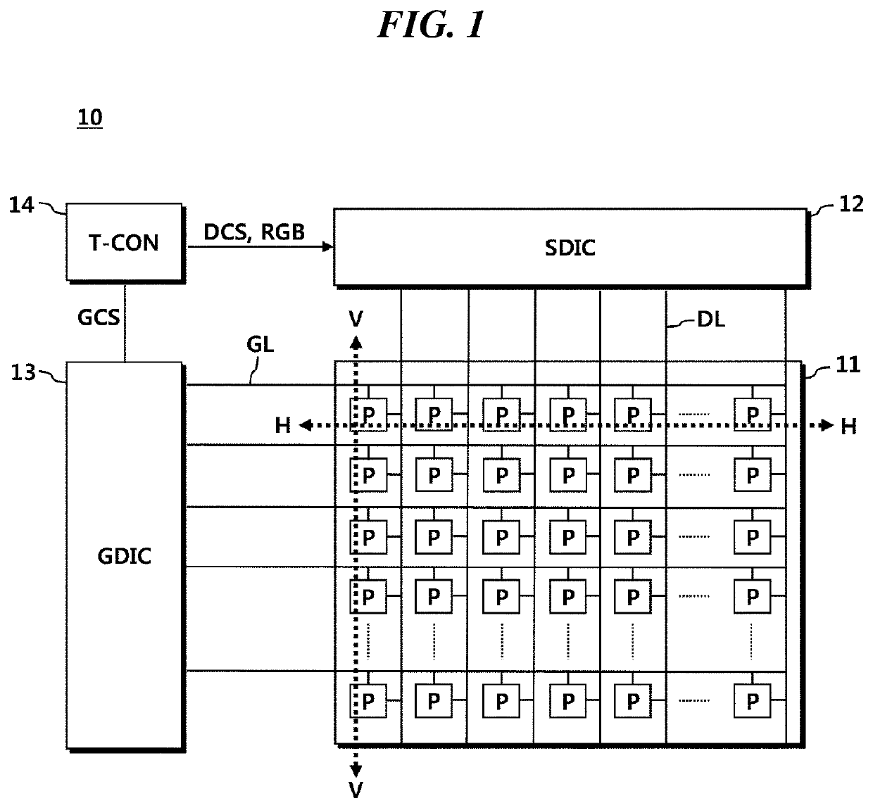
[0042]FIG. 1 is a configuration diagram of a display system according to an embodiment.

[0043]Referring to FIG. 1, a display device 10 may comprise a panel 11, a source driver 12, a gate driver 13, and a timing controller 14.

[0044]On the panel 11, a plurality of data lines DL and a plurality of gate lines GL may be disposed and a plurality of pixels P may also be disposed. The plurality of pixels P may be disposed side by side, in a horizontal direction H, and in a vertical direction V so as to form a square shape as a whole. Since this square shape is similar to a matrix shape, a set of a plurality of pixels P arranged in the horizontal direction H or a horizontal line that the plurality of pixels P form may be referred to as a row or a line, and a set of a plurality of pixels P arranged in the vertical direction V or a vertical line that the plurality of pixels P form may be referred to as a column.

[0045]The gate driver 13 may supply scan signals, such as turn-on voltages or turn-o...


PUM


Abstract

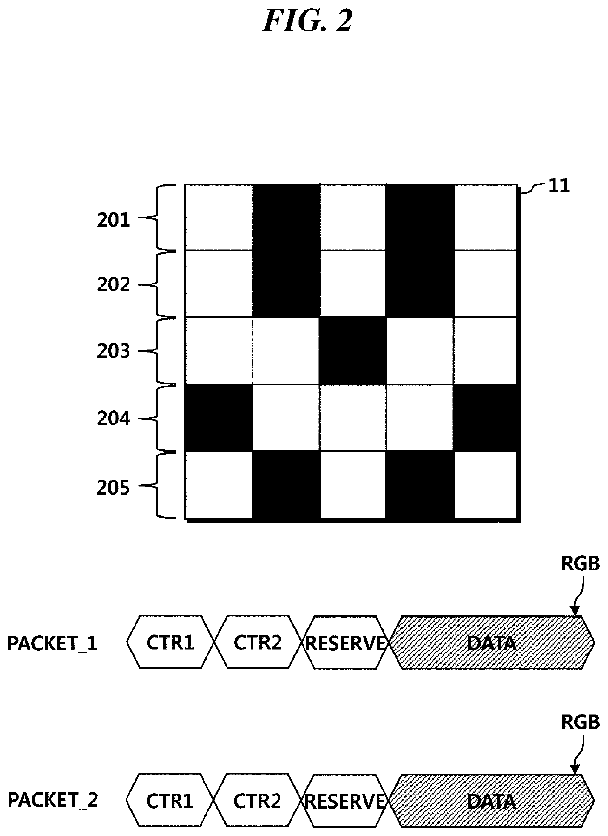
An embodiment of the present disclosure relates to a display device allowing minimizing repetitive transmissions and receptions of identical pieces of image data so as to reduce power consumption due to the repetitive transmissions and receptions of identical pieces of image data.

Description

CROSS REFERENCE TO RELATED APPLICATION[0001]This application claims priority from Republic of Korea Patent Application No. 10-2019-0096770, filed on Aug. 8, 2019, which is hereby incorporated by reference in its entirety.BACKGROUND1. Field of Technology[0002]The present disclosure relates to a display device minimizing repetitive transmissions and receptions of identical pieces of image data.2. Description of the Prior Art[0003]A display device may comprise a panel, a source driver for driving the panel, and a timing controller for controlling the drive of the source driver. A panel comprises a plurality of pixels forming rows and columns that are disposed side by side in a horizontal direction and in a vertical direction so that the plurality of pixels are placed on the panel in a form of a matrix. A row formed by the plurality of pixels when they are disposed in the horizontal direction may also be referred to as a line.[0004]A source driver may simultaneously drive the plurality ...

Claims


Application Information

Patent Timeline
Patent Type & Authority Patents(United States)
IPC IPC(8): G09G3/20
CPCG09G3/20G09G2310/0286G09G2310/0291G09G2310/08G09G2370/08G09G2310/0275G09G2330/06G09G2330/021G09G2320/103G09G3/2092G09G2310/0264G09G2370/16
Inventor CHOI, JUNG MINLEECHOI, JUNG HWAN
Owner SILICON WORKS CO LTD
Learn More