
Method and system for change detection using AR overlays

a technology of ar overlays and methods, applied in the field of augmented reality, can solve problems such as difficult or costly user detection of defects, material or structural collapse, and defects in manufactured products

Active Publication Date: 2022-03-29
XEROX CORP
View PDF11 Cites 0 Cited by
  • Summary
  • Abstract
  • Description
  • Claims
  • Application Information

AI Technical Summary

Benefits of technology

Enhances the accuracy and efficiency of defect detection by leveraging human perception and reducing the reliance on expensive machine vision, while providing a flexible and cost-effective means to identify and quantify changes, facilitating timely maintenance and repair of manufactured products.

Problems solved by technology

However, there are limitations in the technology, which can sometimes lead to defects in the manufactured products.
Such defects can include over or under-deposition of material or structural collapse.
Sometimes the defects can be subtle, and detecting the defect can be difficult or costly to users.
Some systems may rely on advanced machine vision technologies and expensive imaging equipment (e.g., 3D laser scanners, computerized axial tomography (CT) machines, X-ray machines, etc.) to detect such imperfection and defects.

Method used


Image

  • Method and system for change detection using AR overlays
  • Method and system for change detection using AR overlays
  • Method and system for change detection using AR overlays

Examples


Embodiment Construction

[0026]The following description is presented to enable any person skilled in the art to make and use the embodiments, and is provided in the context of a particular application and its requirements. Various modifications to the disclosed embodiments will be readily apparent to those skilled in the art, and the general principles defined herein may be applied to other embodiments and applications without departing from the spirit and scope of the present disclosure. Thus, the present invention is not limited to the embodiments shown, but is to be accorded the widest scope consistent with the principles and features disclosed herein.

Overview

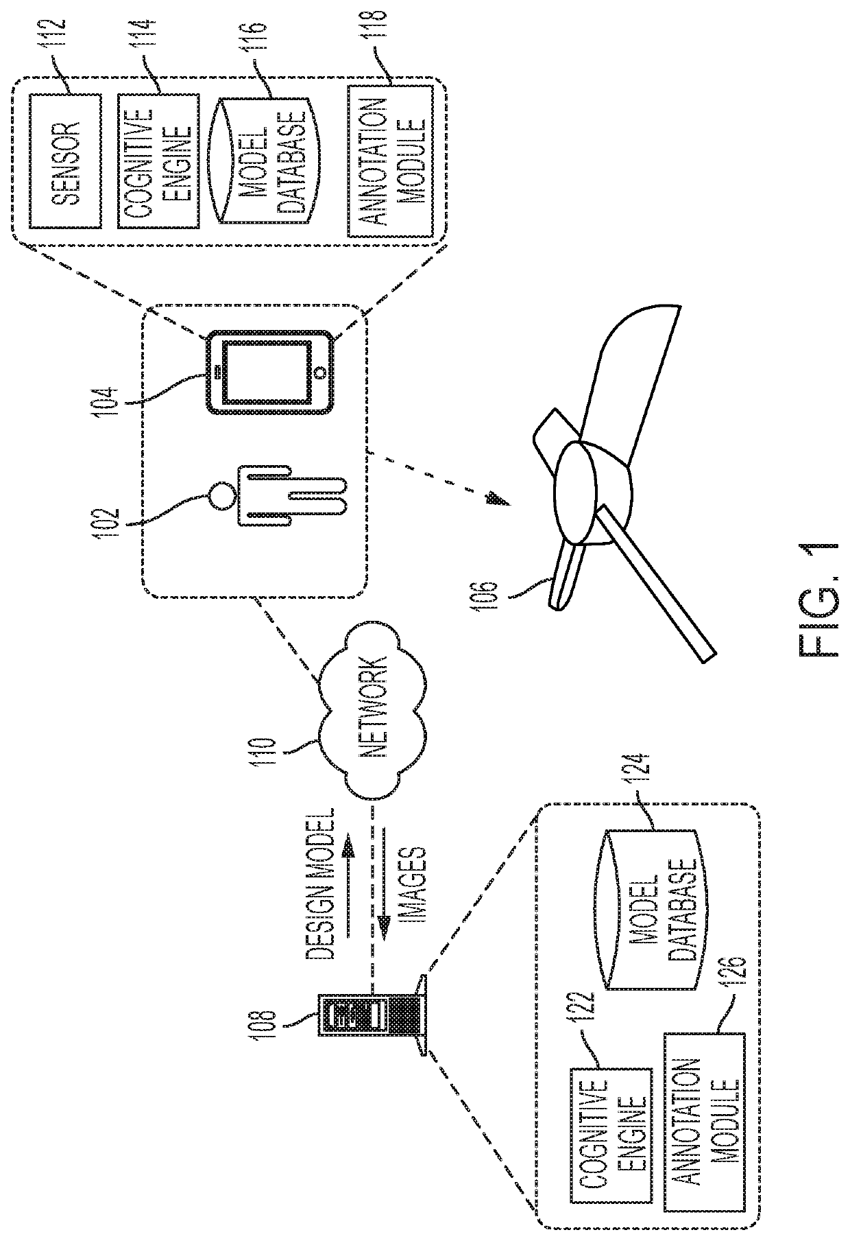
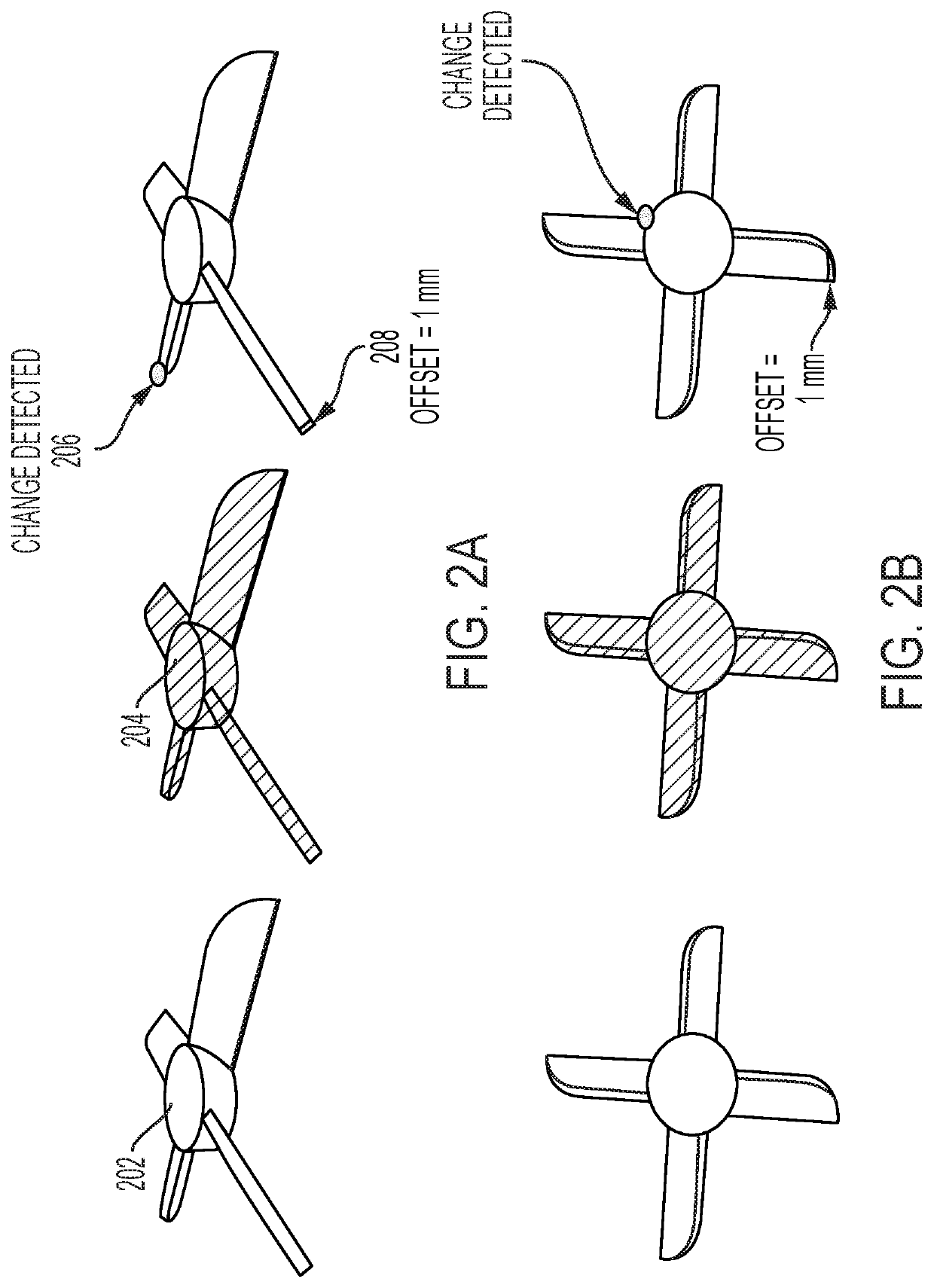
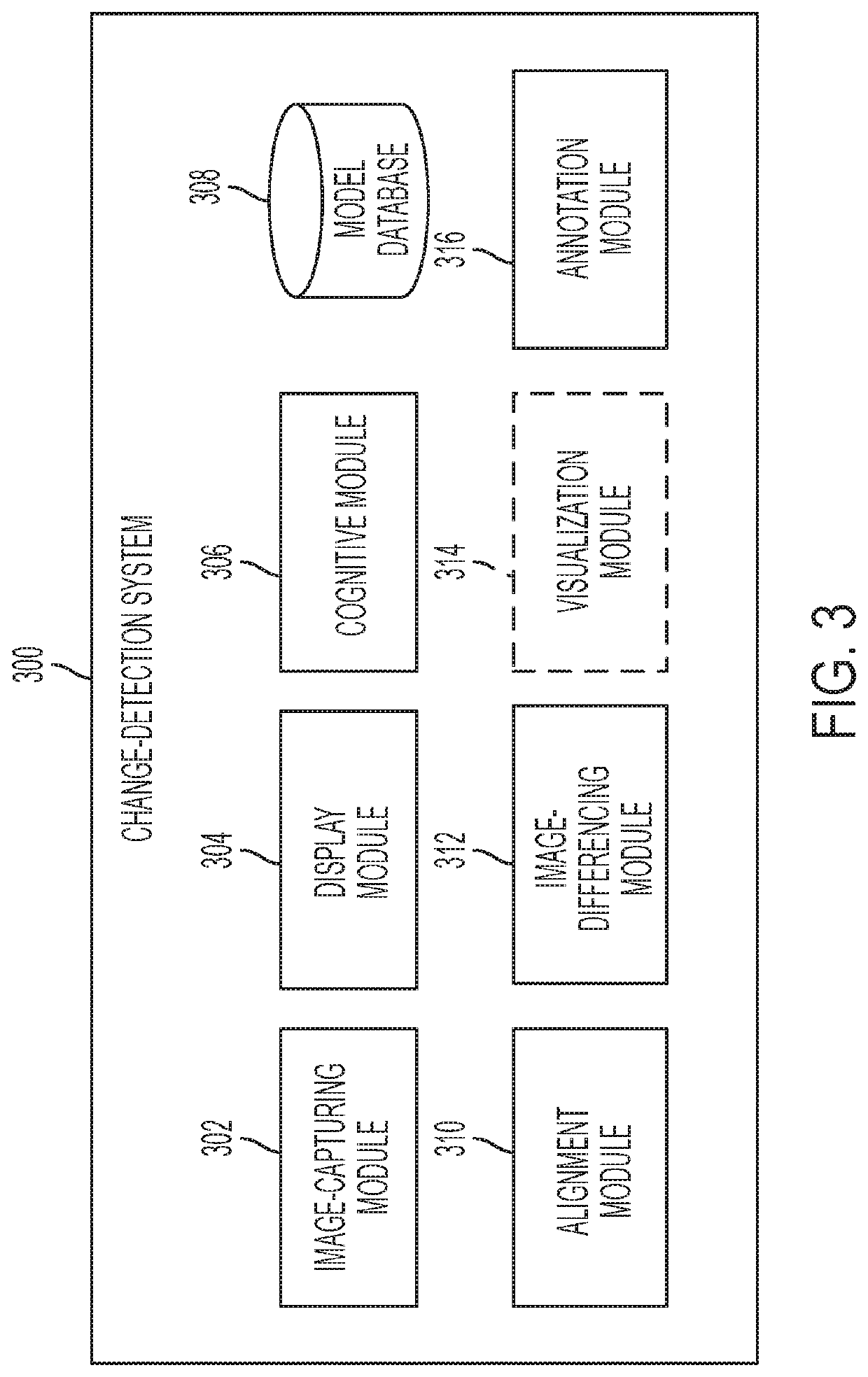
[0027]The embodiments described herein solve the technical problem of detecting changes between the design of a manufactured product and the product itself. In some embodiments, the intelligent change-detection system can harvest the ability of human perception to detect the difference between two images when they overlie one another. More specific...


PUM

PropertyMeasurementUnit
timeaaaaaaaaaa
coloraaaaaaaaaa
color differenceaaaaaaaaaa

Abstract

One embodiment can provide a system for detecting a difference between a physical object and a reference model corresponding to the physical object. During operation, the system obtains a real-world image of the physical object and generates an augmented reality (AR) image by projecting a three-dimensional overlay generated from the reference model onto the physical object in the real-world image. While generating the AR image, the system aligns a pose of the reference model to a pose of the physical object. The system can detect the difference between the physical object and the reference model based on the generated AR image and the real-world image.

Description

BACKGROUNDField[0001]This disclosure is generally related to augmented reality (AR). More specifically, this disclosure is related to a system and method that implements AR overlays to detect changes between a design and a manufactured product.Related Art[0002]In recent years, the rapid development in 3D printing technology, including increased precision, repeatability, and material range, has made 3D printing or additive manufacturing a viable solution in industrial production. 3D printing has found many practical applications beyond rapid prototyping, including food manufacturing, fashion design, car manufacturing, agile tooling, medical applications, etc.[0003]However, there are limitations in the technology, which can sometimes lead to defects in the manufactured products. Such defects can include over or under-deposition of material or structural collapse. Sometimes the defects can be subtle, and detecting the defect can be difficult or costly to users. For example, the thickne...

Claims


Application Information

Patent Timeline
Patent Type & Authority Patents(United States)
IPC IPC(8): G06T7/90G06T7/00B33Y50/00G06T7/136G06T7/13B29C64/386G06T17/20
CPCG06T7/001B29C64/386B33Y50/00G06T7/13G06T7/136G06T7/90G06T17/20G06T2207/20081G06T7/33G06T2207/30144
Inventor SHREVE, MATTHEW A.RYTHEN LARSSON, LISA S. E.
Owner XEROX CORP
Learn More