Electrical harness for a turbomachine

a technology of electric harness and turbomachine, which is applied in the direction of gas turbine type power plants, contact material materials, transportation and packaging, etc., can solve the problems of increasing the size and weight of the harness, affecting and affecting the installation of the turbomachine fixed parts, so as to facilitate the mounting and positioning of the harness. , to achieve the effect of ensuring the electrical continuity of the shielding

Active Publication Date: 2022-03-29
SN DETUDE & DE CONSTR DE MOTEURS DAVIATION S N E C M A
View PDF12 Cites 0 Cited by
  • Summary
  • Abstract
  • Description
  • Claims
  • Application Information

AI Technical Summary

Benefits of technology

[0014]The connecting socket combines the fixing and crimping function of the shielding braids into a single rigid, one-piece element. The crimping part is therefore sufficiently rigid to allow the shielding braids to be crimped with the crimping tool. Such a crimp guarantees the electrical continuity of the shielding.
[0015]In addition, the shape of the attachment part can be fixed, e.g. cylindrical, so as to facilitate mounting and angular positioning of the harness on the relevant part of the turbomachine.
[0027]The second protection tubes can be made of heat-shrinkable synthetic material, e.g. a material marketed under the brand name VITON® by the DuPont de Nemours company. Heat-shrinkable synthetic materials are lightweight and can withstand temperatures up to 210° C. The second protection tubes can also be made of stainless materials, which can withstand temperatures up to 260° C.

Problems solved by technology

The areas where the harness is attached to the fixed parts of the turbomachine may also have defects in shape, due to their structure.
These defects in shape make it more difficult to install them on the turbomachine.
The use of two separate bushings increases the size and weight of the harness, making it difficult to integrate such a harness into a small turbomachine.

Method used


Image

  • Electrical harness for a turbomachine
  • Electrical harness for a turbomachine

Examples


Embodiment Construction

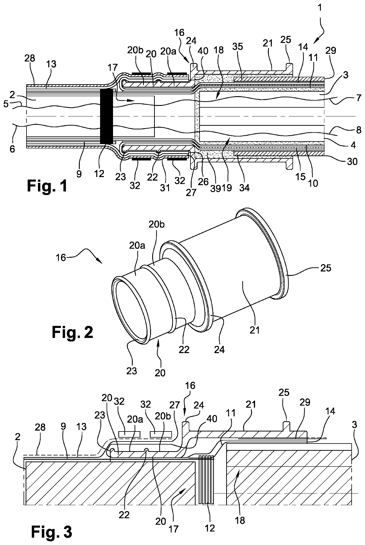
[0038]FIG. 1 shows a part of a harness 1 according to a first embodiment of the invention. The harness consists of a first strand of cables 2 and two second strands of cables 3, 4, which are intended to supply power to components of the turbomachine from a source, or to transfer electrical signals between components. Each cable has at least one electrical conductor. Each electrical conductor 5, 6 of the first cable is branched into the second cable strands 3, 4 consisting of electrical conductors 7, 8.

[0039]The first cable strand 2 and every second cable strand 3, 4 are externally surrounded by a first textile protective braid. The first protective braid 9 of the first cable strand 2 and the first protective braids 10, 11 of the second cable strands 3, 4 are sewn together in an overlap area 12. The overlap area 12 is located outside the first cable strand 2.

[0040]For example, the first protective braids 9, 10, 11 are made of a synthetic material of the meta-aramid type.

[0041]A first...


PUM


Abstract

The present invention relates to an electrical harness (1) comprising at least one first cable strand (2) and at least one second cable strand (3, 4), which are respectively at least partially surrounded externally by a first shielding braid (13) and a second shielding braid (14, 15), and a connecting socket (16) externally surrounding one end of the first cable strand (17) and one end of the second cable strand (18, 19), characterised in that the connecting socket (16) comprises a fixing part (21) intended to be engaged on a fixing member of the turbomachine, and a crimping part (20), the ends (26, 27, 28) of the first (13) and second (14, 15) shielding braids being engaged externally to the crimping part (20), at least one crimping member (32) holding said ends (26, 27, 40) on the crimping part (20).

Description

CROSS-REFERENCE TO RELATED APPLICATIONS[0001]This application is a 35 U.S.C. § 371 filing of International Application No. PCT / FR2019 / 051210 filed May 24, 2019, which claims the benefit of priority to French Patent Application No. 1854464 filed May 25, 2018, each of which is incorporated herein by reference in its entirety.FIELD OF THE INVENTION[0002]The present invention concerns an electrical harness in particular for aeronautics and more particularly intended to be mounted in a turbomachine such as a turbojet or turboprop engine of an aircraft.BACKGROUND OF THE INVENTION[0003]Reducing the dimensions of turbomachinery requires finding electrical harness solutions whose dimensions and characteristics allow them to be mounted in restricted spaces.[0004]In addition, there is a need to develop electrical harnesses that can withstand high temperatures, while being compact and lightweight.[0005]In order to reduce the mass of electrical harnesses, lighter, heat-shrinkable synthetic mater...

Claims


Application Information

Patent Timeline
Patent Type & Authority Patents(United States)
IPC IPC(8): H01R9/05H01R4/20H01R4/18B64D27/10B64D27/16H01R4/58H01R4/72
CPCH01R4/20H01R4/183B64D27/10B64D27/16H01R4/58H01R4/72H02G3/0462H02G3/06B60R16/0215
Inventor MARMET, ERIC MAURICE DANIELAUDOUX, CLÉMENT PIERRE BERNARDMACHADO, VICTORINPAGES, JOCELYN JEAN ROMOLO
Owner SN DETUDE & DE CONSTR DE MOTEURS DAVIATION S N E C M A
Why Eureka
Try Eureka