Dual stator machine with a rotor magnet set configured to minimize flux leakage

a technology of rotor magnets and stator machines, applied in the field of machines, can solve the problems of reducing reliability and adding to system complexity, and achieve the effect of minimizing magnetic flux leakag

Active Publication Date: 2022-03-29
HAMILTON SUNDSTRAND CORP
View PDF43 Cites 0 Cited by
  • Summary
  • Abstract
  • Description
  • Claims
  • Application Information

AI Technical Summary

Benefits of technology

[0023]Further disclosed is a method of minimizing magnetic flux leakage through a permanent magnet machine, comprising: generating a magnetic flux by directing a current between a plurality of inner stator poles and a corresponding plurality of outer stator poles in the machine, and through a plurality of rotor poles therebetween; and guiding the magnetic flux through the plurality of rotor poles utilizing a plurality of flux barrier slots, the plurality of rotor poles and the plurality of flux barrier slots arranged in a circumferentially alternating sequence, one after another, such that each of the plurality of rotor magnets is circumferentially bounded by a pair of the plurality of flux barrier slots, and a portion of one of the plurality of rotor magnets is disposed along a machine radial axis and / or a portion of the plurality of flux barrier slots is disposed at an angle to a machine radial axis.

Problems solved by technology

Direct-drives eliminate the need for gear boxes, which otherwise add to system complexity and reduce reliability due to increased parts.

Method used


Image

  • Dual stator machine with a rotor magnet set configured to minimize flux leakage
  • Dual stator machine with a rotor magnet set configured to minimize flux leakage
  • Dual stator machine with a rotor magnet set configured to minimize flux leakage

Examples


Embodiment Construction

[0033]A detailed description of one or more embodiments of the disclosed apparatus and method are presented herein by way of exemplification and not limitation with reference to the Figures.

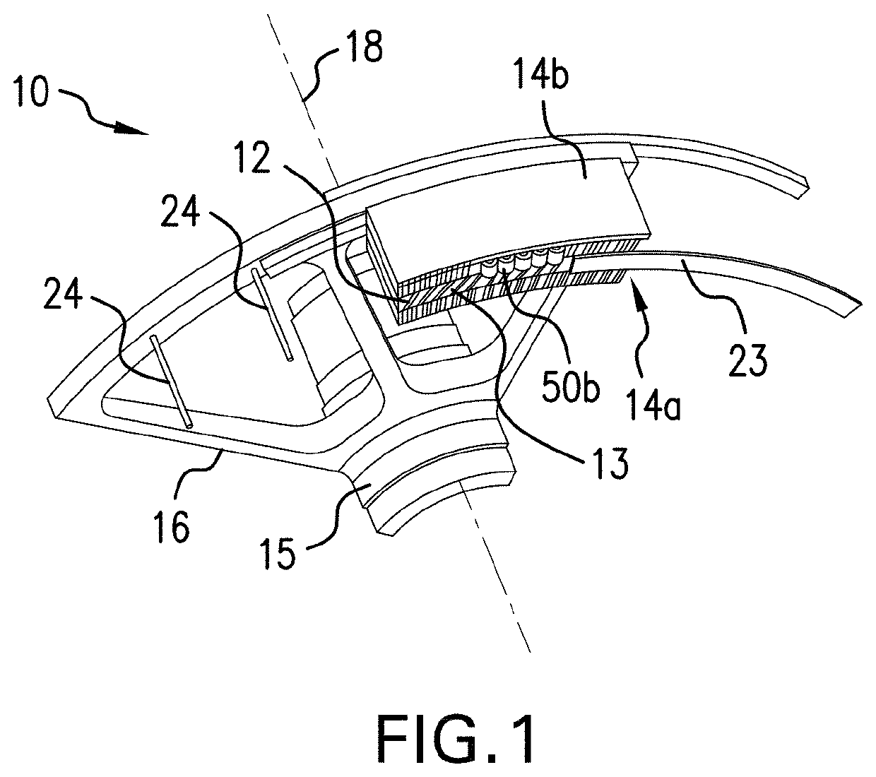
[0034]Referring to FIG. 1 an electric machine (machine) 10a is illustrated. The machine 10a includes a rotor 11 including a rotor magnet set 12 supported by a rotor body extension 13 that is annularly shaped. The rotor body extension 13 extends from a rotor support 15 that extends radially. The rotor support 15 is connected to a rotor shaft 15 that extends axially. The machine 10a includes and a plurality of stators 14 including an inner stator 14a and an outer stator 14b. The machine 10a may be operated as an electric motor, or as an electric generator.

[0035]Generally, the rotor body extension 13 and the stators 14 are concentric and axially-aligned relative to an axial centerline 18 of the machine 10. The rotor 11 rotates relative to the stators 14 which are positionally-fixed to a housing (not...


PUM


Abstract

Disclose is a machine including: an inner stator having a plurality of radially outwardly extending teeth; an outer stator having a plurality of radially inwardly extending teeth that are offset from the radially outwardly extending teeth; a rotor including an extension between the plurality of stators, the extension including a plurality of rotor magnet slots and a plurality of flux barrier slots; the plurality of rotor magnet slots and the plurality of flux barrier slots contact one another and are arranged in a circumferentially alternating sequence, one after another, such that each of the rotor magnet slots is circumferentially bounded by a pair of the flux barrier slots; and a portion of each of the plurality of rotor magnet slots is disposed along a machine radial axis and / or a portion of each of the plurality of flux barrier slots is disposed at an angle to the machine radial axis.

Description

BACKGROUND[0001]Exemplary embodiments pertain to the art of machines and more specifically to a dual stator machine with a rotor magnet set configured to minimize flux leakage.[0002]A Vernier machine (VM) is a type of synchronous reluctance machine where the rotor rotates relatively at a fraction of the angular velocity of the stator's rotating field. Torque is developed based on an interaction between a field created by current in stator windings and the magnetic flux from rotor mounted permanent magnets. In VMs, the machine torque steps up as the rotor speed steps down, creating an electric gearing effect. This makes the VM a useful topology for direct-drive applications. Direct-drives eliminate the need for gear boxes, which otherwise add to system complexity and reduce reliability due to increased parts.BRIEF DESCRIPTION[0003]Disclose is a machine comprising: an inner stator having a plurality of radially outwardly extending teeth; an outer stator having a plurality of radially ...

Claims


Application Information

Patent Timeline
Patent Type & Authority Patents(United States)
IPC IPC(8): H02K1/27H02K16/04H02K1/276H02K1/30H02K35/02
CPCH02K16/04H02K1/2766H02K1/30H02K35/02H02K1/27H02K21/12H02K1/20H02K2213/03
Inventor TANGUDU, JAGADEESH KUMAR
Owner HAMILTON SUNDSTRAND CORP
Why Eureka
Try Eureka