

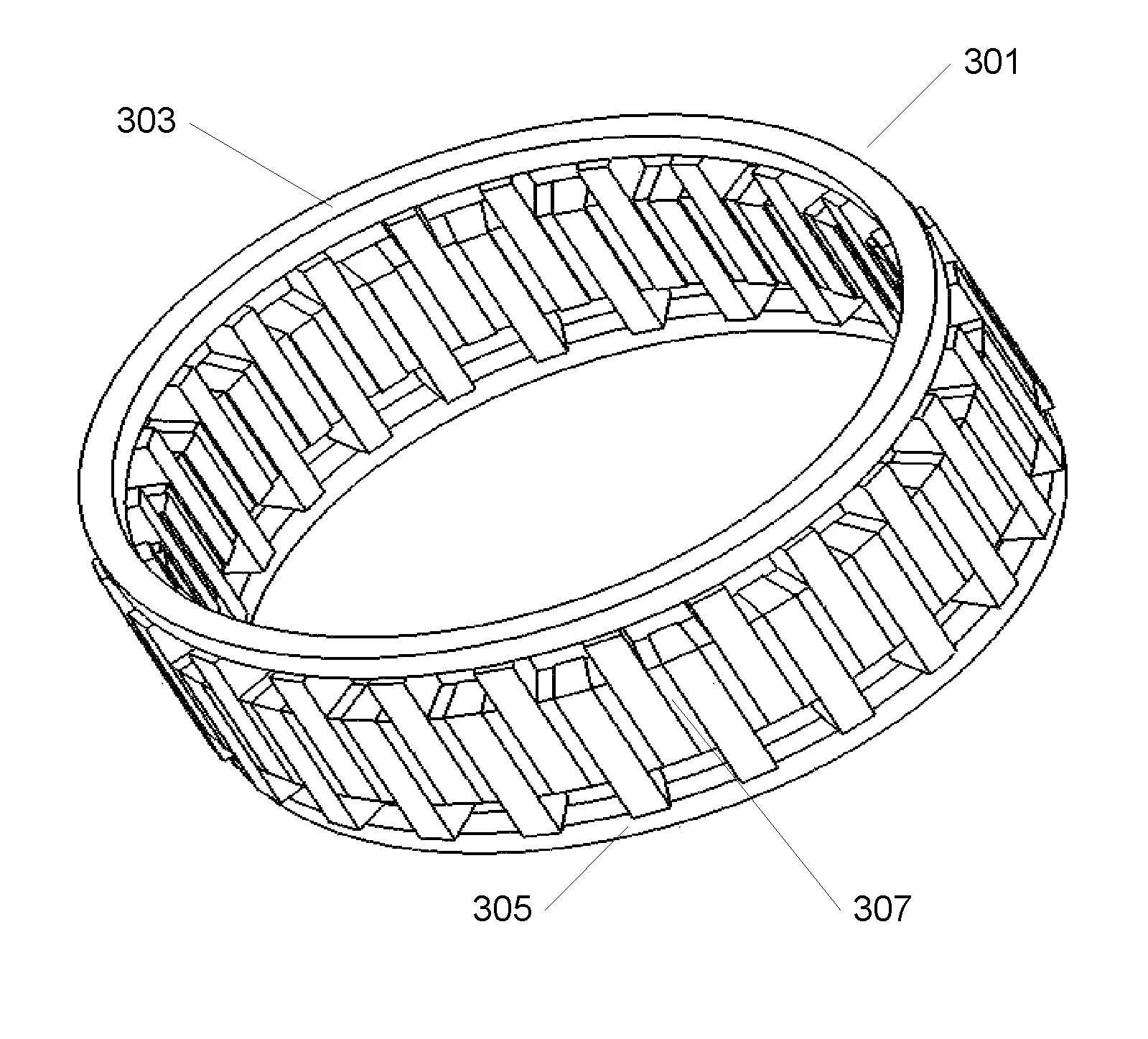
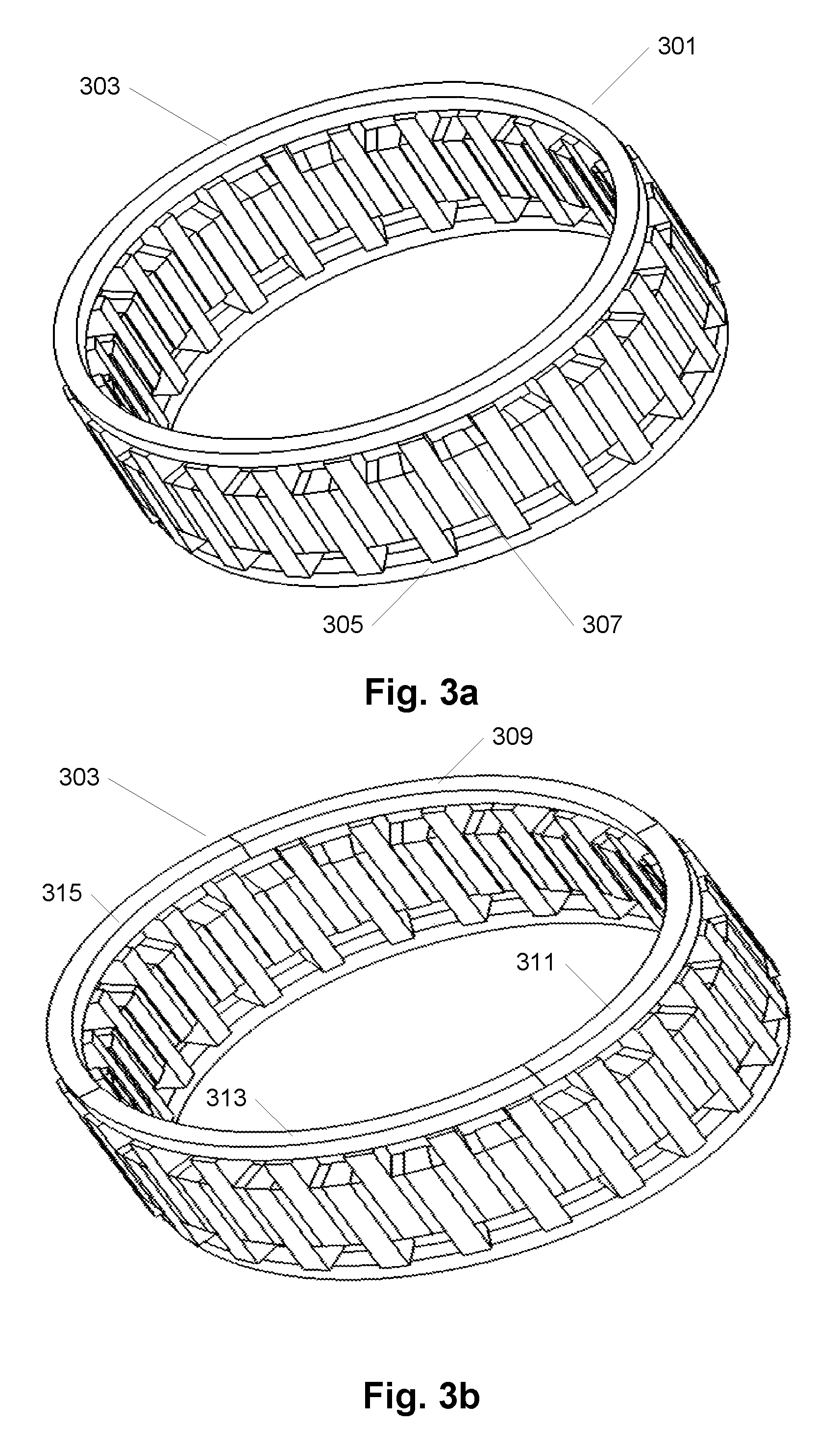
Integrated rotor pole pieces
a rotor and pole technology, applied in the direction of rotating magnets, magnetic circuit rotating parts, synchronous machines with stationary armatures, etc., can solve the problems of increasing the volume, weight and cost of the total drive, and low power factor, so as to facilitate the assembly of the rotor and increase the precision
- Summary
- Abstract
- Description
- Claims
- Application Information
AI Technical Summary
Benefits of technology
Problems solved by technology
Method used
Image

Examples
Embodiment Construction
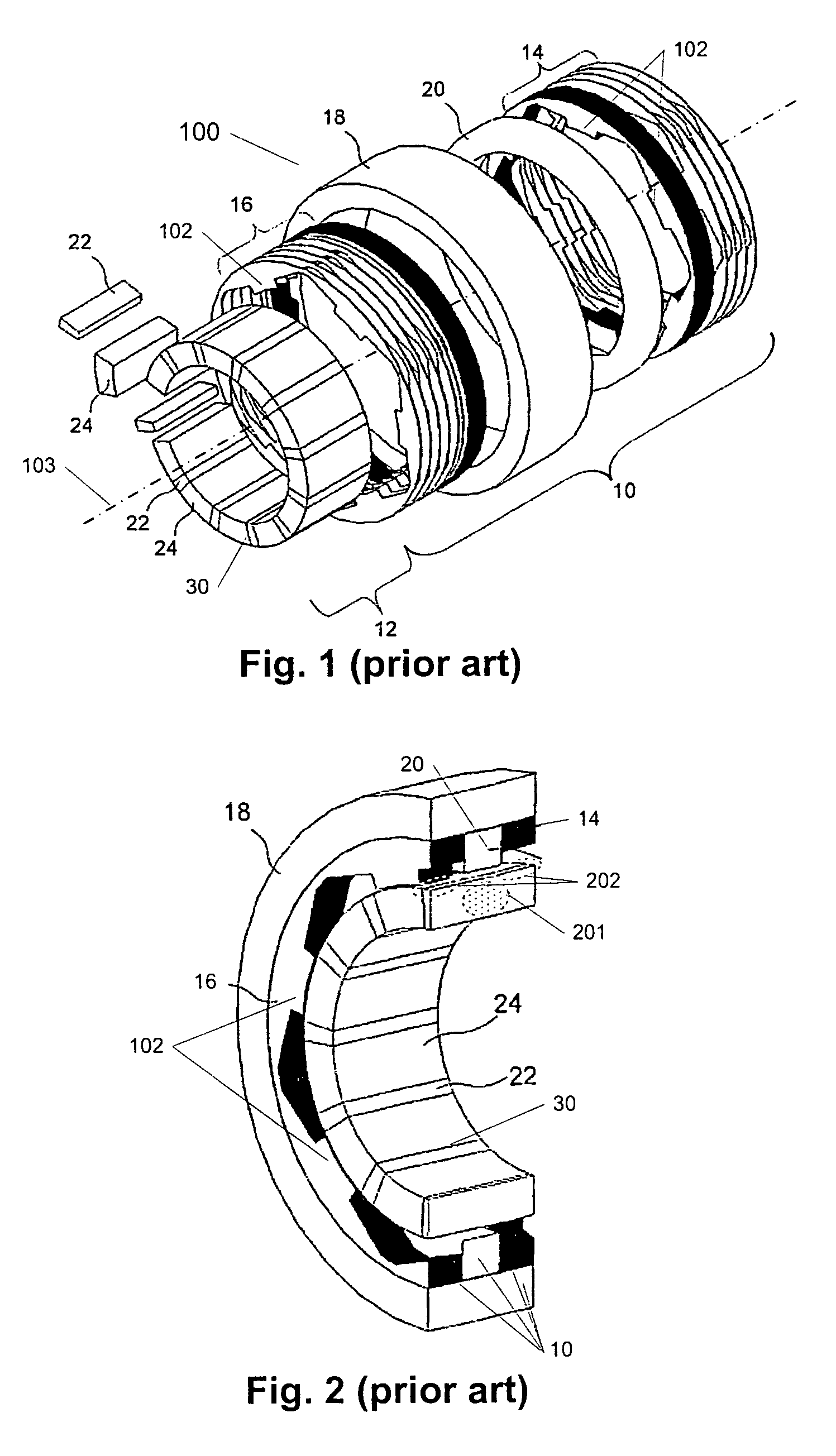
[0040]This invention is in the field of a modulated pole electric machine 100 of which one example is shown in FIG. 1 in a schematic, exploded, perspective view. The modulated pole electric machine stator 10 is basically characterised by the use of a central single winding 20 that will magnetically feed multiple teeth 102 formed by the soft magnetic core structure. The stator core is then formed around the winding 20 while for other common electrical machine structures the winding is formed around the individual tooth core section. Examples of the modulated pole machine topology are sometimes recognised as e.g. Claw-pole-, Crow-feet-, Lundell- or TFM-machines. More particularly the shown modulated pole electric machine 100 comprises two stator core sections 14, 16 each including a plurality of teeth 102 and being substantially circular, a coil 20 arranged between the first and second circular stator core sections, and a rotor 30 including a plurality of permanent magnets 22. Further...
PUM
| Property | Measurement | Unit |
|---|---|---|
| particle sizes | aaaaa | aaaaa |
| particle sizes | aaaaa | aaaaa |
| angle | aaaaa | aaaaa |
Abstract
Description
Claims
Application Information