
Rotor drive applied to drive motor with a structure in which removes a fixation jaws for holding a permanent magnet

a technology of permanent magnet and rotor, which is applied in the direction of magnetic circuit rotating parts, magnetic circuit shapes/forms/construction, electric devices, etc., can solve the problems of small drive motors that have to be designed, reduce torque density, and material cost of drive motors, so as to reduce minimize the leakage of magnetic flux of drive motors. , the effect of reducing the number of fixation jaws

Active Publication Date: 2021-06-17
HYUNDAI MOTOR CO LTD +1
View PDF0 Cites 2 Cited by
  • Summary
  • Abstract
  • Description
  • Claims
  • Application Information

AI Technical Summary

Benefits of technology

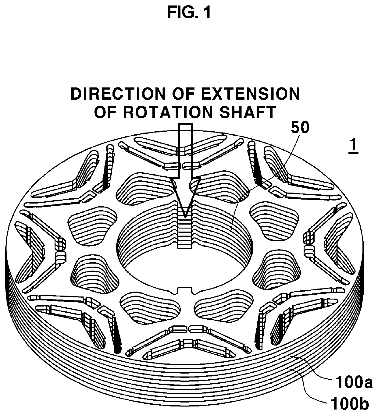
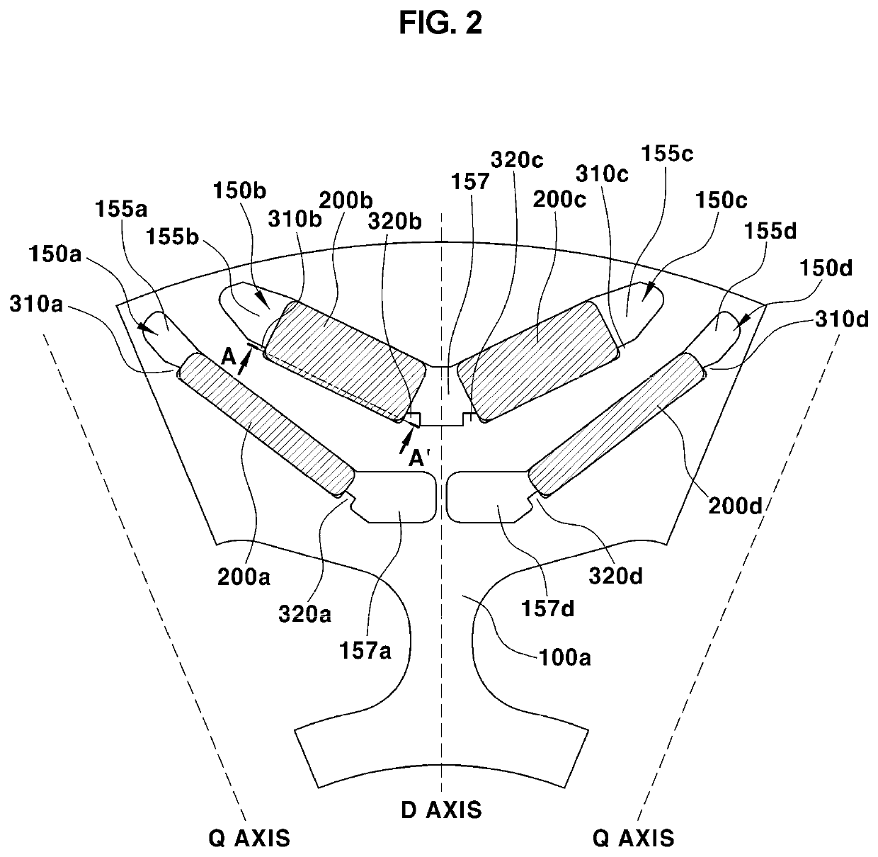
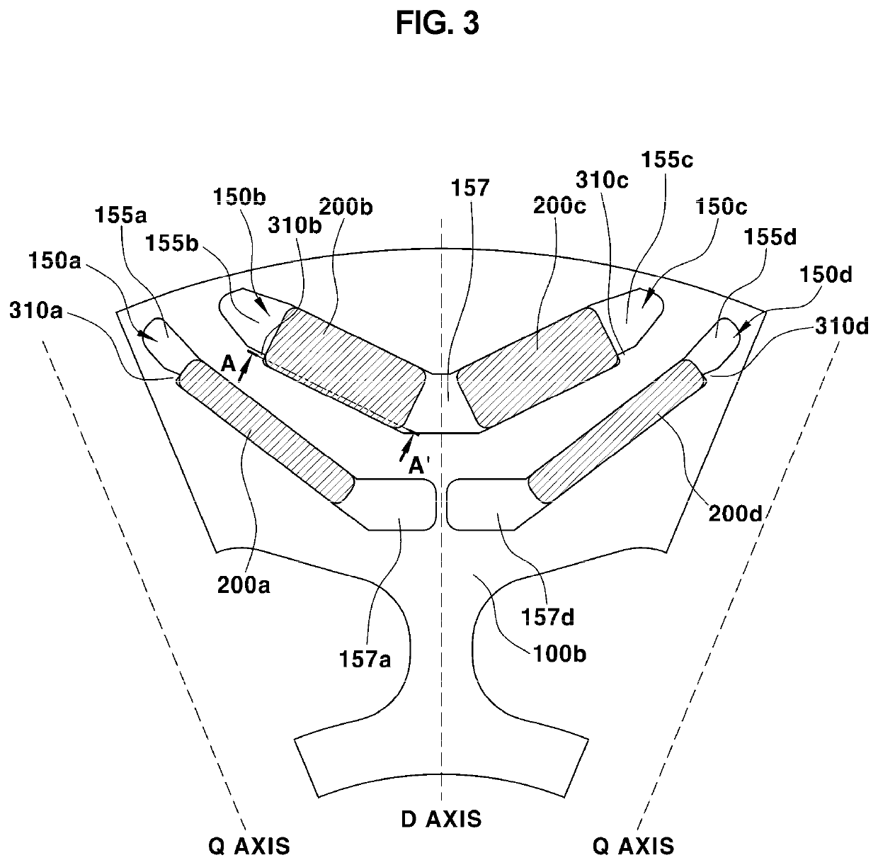
The present disclosure provides a rotor for a drive motor that can minimize magnetic flux leakage, which is achieved by reducing the number of fixation jaws that hold the permanent magnets in place. The rotor includes two cores with different numbers of fixation jaws mixed together, which reduces the leakage of magnetic flux. Additionally, the rotor design includes a second core with no second fixation jaw, which further reduces magnetic flux leakage. The design also maintains holding forces that hold the permanent magnets in place.

Problems solved by technology

However, in order to provide large amounts of torque and output within a limited space in a vehicle, smaller-sized drive motors have to be designed.
However, as leakage of a magnetic flux increases at a position where the fixation jaw is provided, torque density decreases.
In a case where an amount of usage that the permanent magnet experiences is increased in order to compensate for a decrease in the torque of the drive motor, an increase in a material cost for the drive motor leads to a decrease in cost competitiveness.

Method used


Image

  • Rotor drive applied to drive motor with a structure in which removes a fixation jaws for holding a permanent magnet
  • Rotor drive applied to drive motor with a structure in which removes a fixation jaws for holding a permanent magnet
  • Rotor drive applied to drive motor with a structure in which removes a fixation jaws for holding a permanent magnet

Examples


Embodiment Construction

[0029]Advantages and features of the present disclosure, and methods of achieving the advantages and the features will be apparent from the accompanying drawings and from embodiments that will be described in detail below. However, the present disclosure is not limited to the embodiments that will be disclosed below, and various different embodiments thereof can be realized. The embodiments are provided to make a complete disclosure of the present disclosure and to put a person of ordinary skill in the art to which the present disclosure pertains on full notice as to the scope of the disclosure. However, the scope of the present disclosure should be only defined in claims. The same reference character throughout the specification refers to the same constituent element.

[0030]In addition, in order to distinguish among constituent elements that have the same name, the terms first, second, and so on are used throughout the present specification. In the following description, no limitati...


PUM


Abstract

Provided is a rotor for application in a drive motor that includes multiple cores of the rotor that define a plurality of slots into each of which a permanent magnet is inserted, in which the cores of the rotor include a first core in which fixation jaws for holding in place one surface of the permanent magnet and the other surface opposite to the one surface in a direction of extension of the permanent magnet are disposed, and a second core in which fixation jaws for holding in place one surface of the one surface of the permanent magnet and the other surface opposite to the one surface in the direction of the extension of the permanent magnet are disposed.

Description

CROSS REFERENCE TO RELATED APPLICATIONS[0001]The present application claims priority to Korean Patent Application No. 10-2019-0168626, filed Dec. 17, 2019, the entire contents of which is incorporated herein for all purposes by this reference.BACKGROUNDField[0002]The present disclosure relates to a rotor in which cores of the rotor, each with fixation jaws for holding a permanent magnet in place, are stacked. More particularly, the present disclosure relates to a rotor for application in a drive motor, in which cores of the rotor have different numbers of fixation jaws.Description of the Related Art[0003]High efficiency and output density are required of a drive motor for application in environment-friendly vehicles. Particularly, electric vehicles (EV) are required to obtain all vehicle motive-power from a drive motor, and therefore, required amounts of torque and output of the drive motor are further increased. In the past, the electric vehicles were limited to a passenger vehicle...

Claims


Application Information

Patent Timeline
IPC IPC(8): H02K1/27H02K1/30H02K21/16H02K15/03
CPCH02K1/2766H02K15/03H02K21/16H02K1/30H02K1/276H02K1/28Y02T10/64H02K21/14B60L2220/10
Inventor PARK, KYUNG SOOLEE, JUNG WOO
Owner HYUNDAI MOTOR CO LTD
Learn More