Asymmetric co-rotating multi-screw extrusion device, extruder and processing method thereof

a multi-screw, asymmetric technology, applied in the field of multi-screw extrusion devices, can solve the problems of limited material melting and mixing effect in the extruder, fluctuation in product performance, etc., and achieve the effects of reducing the use of kneading blocks, accelerating melting, and remarkable energy saving effects

Active Publication Date: 2022-04-05
WUYI UNIV
View PDF4 Cites 0 Cited by
  • Summary
  • Abstract
  • Description
  • Claims
  • Application Information

AI Technical Summary

Benefits of technology

[0004]The present disclosure aims to solve at least one of the technical problems described above in related art to some extent. For this purpose, the present disclosure provides an asymmetric co-rotating multi-screw extrusion device, wherein each of the screws has a cross-sectional profile comprising one or more circular arcs between a root and a crest thereof, to break the symmetry. Resulting from above, the screws inter-meshed with each other can have different shapes and different axial opening degrees of flow channels in the upper and the lower intermeshing areas, thus to provide a back mixing effect in the axial direction, which can improve melting, mixing and exhaust efficiencies.
[0025]One or more technical solutions in the present disclosure at least have the following beneficial effects:
[0026]1. According to the present disclosure, each of the first screw and the second screw has one or more circular arc pairs between the root and the crest in the cross-sectional profile thereof to break the symmetry. The corresponding circular arc pairs are tangentially inter-meshed, allowing the screws inter-meshed with each other to have different shapes and different axial opening degrees in the upper and lower intermeshing areas of the flow channels, and thereby to introduce an enhancement mechanism of axial back mixing to effectively accelerate the melting, plasticizing, mixing and exhaust efficiencies;
[0027]2. According to the present disclosure, the screw mechanism ensures that the first screw and the second screw are tightly inter-meshed and co-rotate at the same speed. The two screws are constructed to wipe with each other, thus realizing a self-cleaning effect in a processing operation.
[0028]3. The present disclosure can greatly reduce the use of a kneading block, has a remarkable energy-saving effect, makes residence time distribution in the processing process narrower, and improves the processing efficiency and effect.

Problems solved by technology

The extruder has a twin-screw intermeshing area which is a key part for melting and mixing, however, the existence of the symmetry leads the screws to have the same intermeshing mode in the intermeshing areas, and the local stacking and deceleration of materials lead to a relaxation effect, the improvement of melting and mixing effects of materials in the extruder is thus limited.
During the melting and mixing processes of materials, there exist independent topological flow channels, and there is almost no axial back mixing between the flow channels, which also leads to fluctuation in product performance caused by component fluctuation during a metering-feeding process of materials.

Method used


Image

  • Asymmetric co-rotating multi-screw extrusion device, extruder and processing method thereof
  • Asymmetric co-rotating multi-screw extrusion device, extruder and processing method thereof
  • Asymmetric co-rotating multi-screw extrusion device, extruder and processing method thereof

Examples


first embodiment

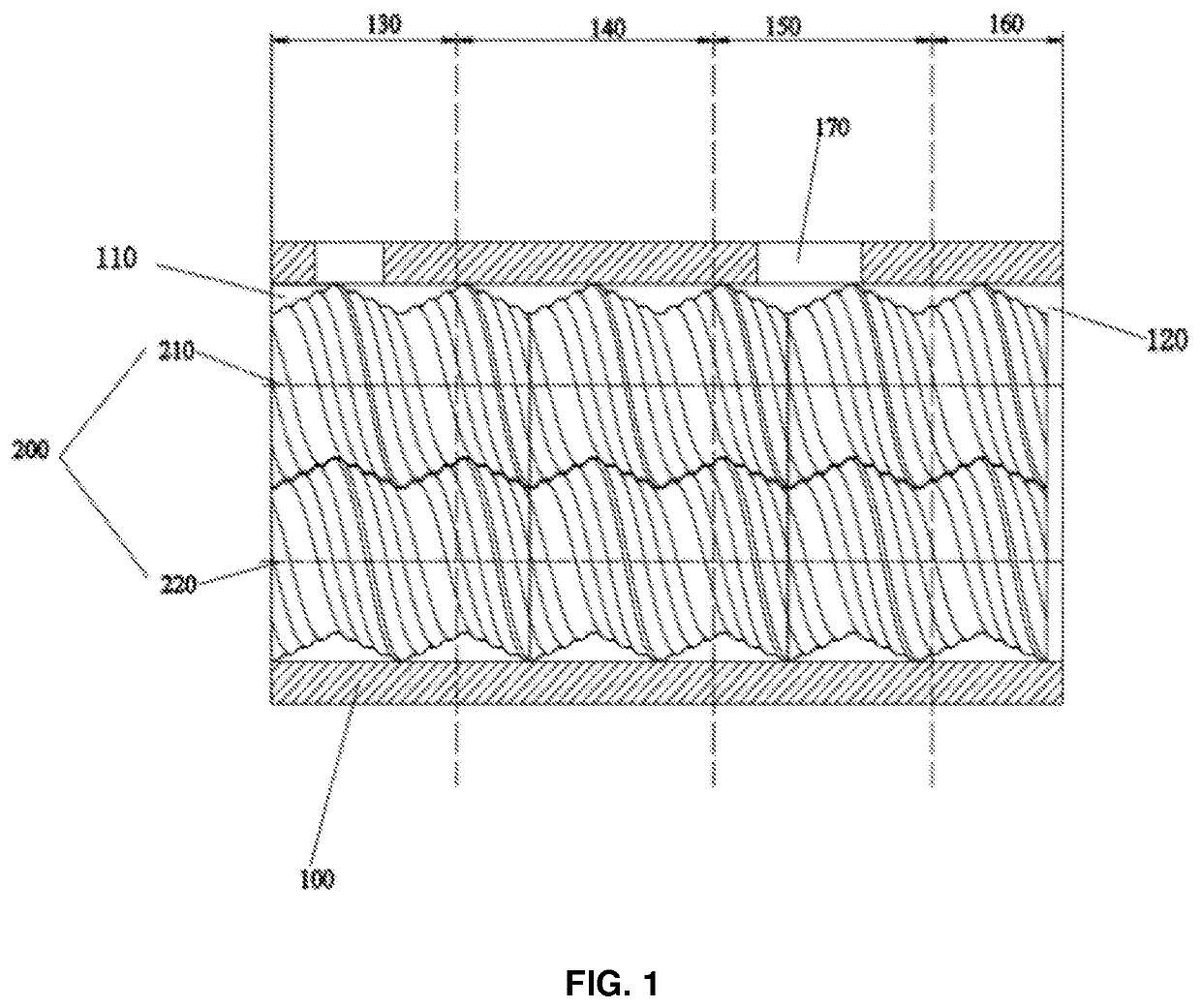
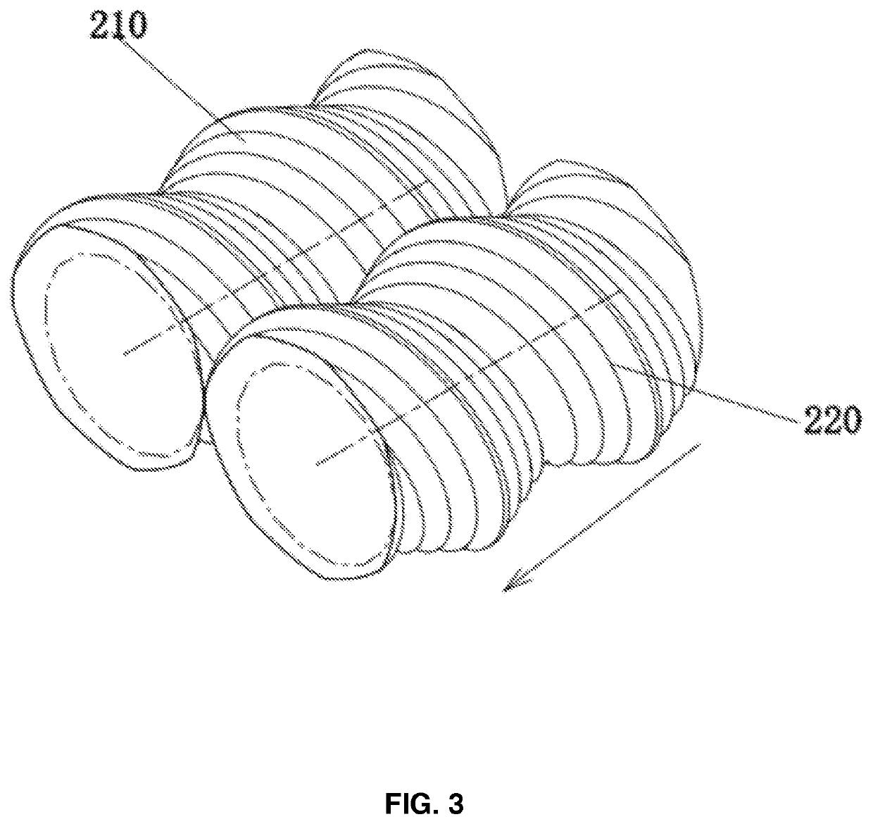
[0048]According to the present disclosure, the device comprises a first screw 210 and a second screw 220 which are inter-meshed with each other, as shown in FIG. 3, and has an axially opened upper intermeshing area, as shown in FIGS. 3 and 4, and an axially opened lower intermeshing area, as shown in FIG. 5. The first screw 210 and the second screw 220 and the inner cavity of the barrel form a flow channel together. When the first screw 210 and the second screw 220 co-rotate at the same speed, the two screws always keep in intermeshing contact with each other to realize a self-cleaning function. As shown in FIGS. 1 to 5, the spirals of the first screw 210 and the second screw 220 are both spiral structures with smooth edges.

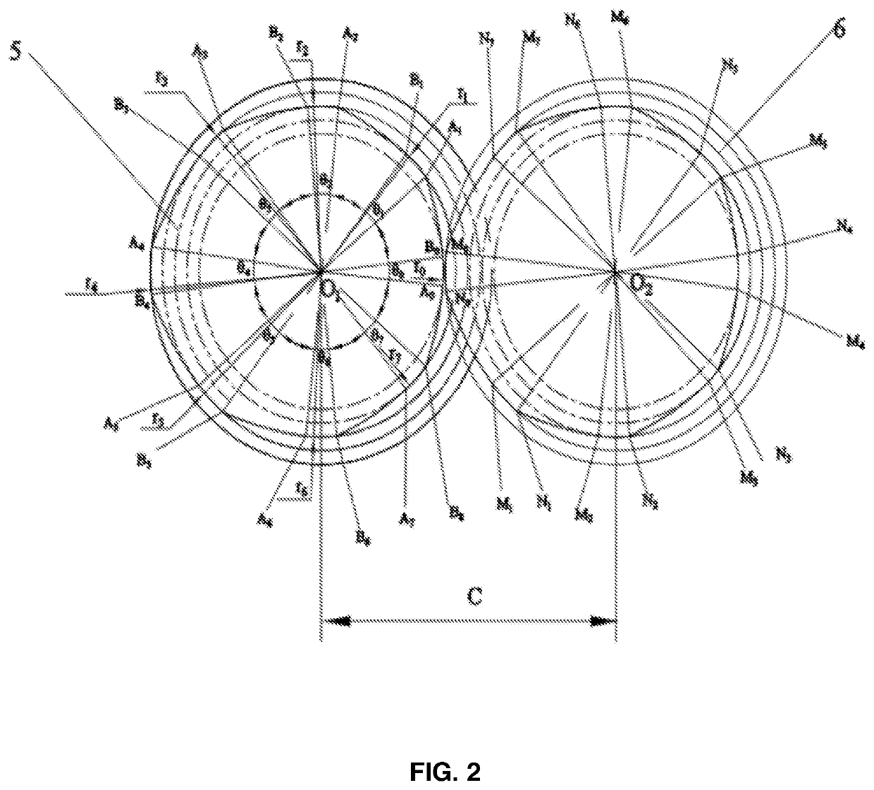
[0049]The first screw 210A may be a single-head threaded component, six circular arcs with a radius ri are introduced in between the root and the crest in the cross-sectional profile of the first screw 210, wherein i=1, 3 and i=5, 7, and d / 2=r01234=D / 2>r5>r6>r7. ...

second embodiment

[0063]Further, according to the present disclosure, as shown in FIGS. 6 and 7, three circular arcs are formed between the root and the crest in the cross-sectional profile of each of the screws, thereby realizing the connection of four curved arcs at intervals. As thus, the screw has the cross-sectional profiles consisting of five circular arcs and five curved arcs. Corresponding circular arc pairs are tangentially inter-meshed, the screws inter-meshed with each other have different shapes and different axial opening degrees of flow channels in upper and lower intermeshing areas, and whereby a strengthening mechanism of axial back mixing is brought to effectively accelerate the melting, plasticizing, mixing, and exhaust efficiencies.

third embodiment

[0064]Further, according to the present disclosure, as shown in FIGS. 8 and 9, three circular arcs with an arc length 0 are formed between the root and the crest in the cross-sectional profile of each of the screws to realize the direct connection of four curved arcs. As thus, the screw has a cross-section consisting of two circular arcs and five curved arcs.

[0065]Further, according to the third embodiment of the present disclosure, as shown in FIG. 10, the screw mechanism 200 further comprises a third screw 230 asymmetrically inter-meshed with the first screw 210 or the second screw 220. The third screw 230 has a cross-sectional profile comprising one or more circular arcs between the root and the crest of the third screw 230. The third screw 230 has the same structure as that of the first screw 210. The first screw 210, the second screw 220, and the third screw 230 are connected in sequence to form a three-screw arrangement in a straight line. The screws have asymmetric intermeshi...


PUM

PropertyMeasurementUnit
speedaaaaaaaaaa
shapeaaaaaaaaaa
stagger angleaaaaaaaaaa

Abstract

Disclosed is an asymmetric co-rotating multi-screw extrusion device, an extruder, and a processing method thereof. The barrel is provided with a feed port located at one end of the screw mechanism and a discharge port located at the other end of the screw mechanism, and the barrel comprises a conveying section, a melting section, an exhaust section, and a mixing extrusion section sequentially arranged from a side thereof where the feed port is located, wherein the exhaust section is provided with an exhaust hole. The screw mechanism comprises at least a first screw and a second screw arranged parallel to the first screw, wherein at least one of the first screw and the second screw has a cross-sectional profile comprising an arc forming a radial step between a root and a crest thereof, and the first screw and the second screw are asymmetrically inter-meshed and co-rotated at the same speed.

Description

CROSS REFERENCE TO RELATED APPLICATION[0001]This application claims the benefit of CN patent application No. 201910683573.1 filed on Jul. 26, 2019, the entire disclosure of which is hereby incorporated herein by reference.BACKGROUND OF THE INVENTIONField of the Invention[0002]The present disclosure relates to the field of multi-screw extruder technologies, and more particularly, to an asymmetric co-rotating multi-screw extrusion device, an extruder, and a processing method thereof.Description of the Related Art[0003]A co-rotating twin-screw extruder with a self-cleaning function mainly comprises a barrel and two screws installed in an inner cavity of the barrel in parallel. The two screws rotate at the same speed and sweep with each other to realize the self-cleaning function. Generally speaking, the left and right screws of the co-rotating screws have a completely identical shape, except that the screws are arranged at a stagger angle. For a single screw, its cross-sectional geomet...

Claims


Application Information

Patent Timeline
Patent Type & Authority Patents(United States)
IPC IPC(8): B29C48/52B29C48/405B29C48/595
CPCB29C48/52B29C48/405B29C48/595B29C48/565B29C48/64B29C48/425
Inventor XU, BAIPINGYU, HUIWENLIU, BIAOXIAO, SHUPINGDU, YAOXUE
Owner WUYI UNIV
Why Eureka
Try Eureka