Eureka AIR delivers breakthrough ideas for toughest innovation challenges, trusted by R&D personnel around the world.

Blood flow measurement apparatus and method

a technology of blood flow and measurement apparatus, which is applied in the field of improved blood flow measurement apparatus and method, can solve the problems of increased cost, limited screening, and a major risk factor of diabetes mellitus

Active Publication Date: 2022-04-05
UNIV OF SOUTH ALABAMA
View PDF15 Cites 2 Cited by
  • Summary
  • Abstract
  • Description
  • Claims
  • Application Information

AI Technical Summary

Benefits of technology

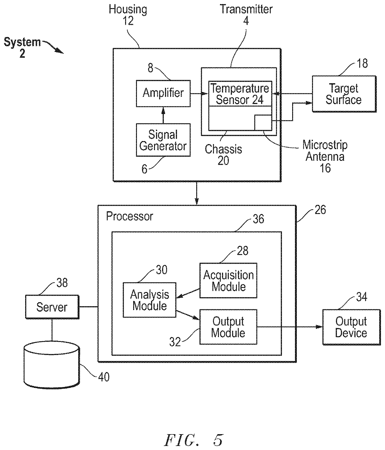
The present invention is an improved skin blood flow measurement apparatus that uses RF energy to measure blood flow in a specific area of the skin. The apparatus includes a chassis with an antenna and a temperature sensor, both of which are fixed in relation to the skin surface. The apparatus also includes a surface support that contacts the skin surface and supports the chassis body above the skin surface. The antenna is designed to operate in the frequency range of 26.5 GHz to 40 GHz. The apparatus can be used non-invasively and provides accurate results.

Problems solved by technology

Diabetes mellitus is a major risk factor for PAD.
Screening is limited and most are not diagnosed until they present with complications (claudication, skin ulcers) (Mohler et al.
This often necessitates aggressive treatment, with higher costs and poorer outcomes than could be obtained with earlier interventions.
This presents a prospectively enormous resource challenge and cost to primary care providers and clinics.
ABI measurement is slow, cumbersome, requires specialized training and is not generally reimbursable (Kuller 2001; Mohler et al.
Current embodiments of the radio frequency (RF) / MMW flow sensing technology require bulky, expensive hardware that is not suitable for point-of-care use.
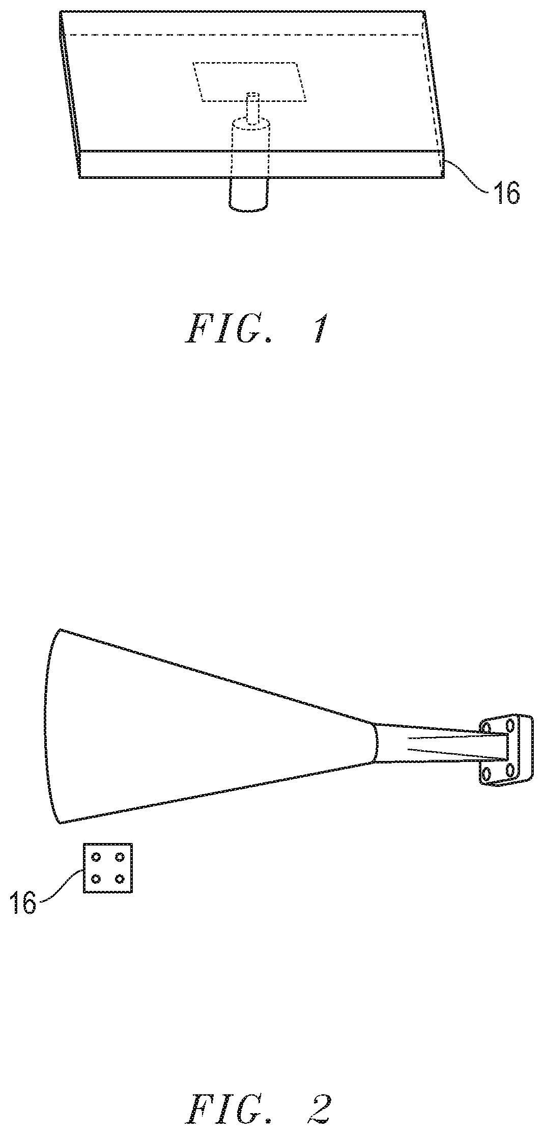
That is, the current state of the art transmitter and sensor system for RF / MMW assessment of skin blood flow relies on a bulky and expensive horn antenna to irradiate the skin surface while monitoring the skin surface temperature with a separate infrared (IR) camera or similar device.
As a result the procedure is slow and has poor repeatability due to inconsistent heating due to positioning errors among other reasons.

Method used


Image

  • Blood flow measurement apparatus and method
  • Blood flow measurement apparatus and method
  • Blood flow measurement apparatus and method

Examples


Embodiment Construction

[0040]Before explaining at least one embodiment of the invention in detail, it is to be understood that the invention is not limited in its application to the details of construction and to the arrangements of the components set forth in the following description or illustrated in the drawings. The invention is capable of other embodiments and of being practiced and carried out in various ways. Also, it is to be understood that the phraseology and terminology employed herein are for the purpose of description and should not be regarded as limiting.

[0041]As such, those skilled in the art will appreciate that the conception, upon which this disclosure is based, may readily be utilized as a basis for the designing of other structures, methods and systems for carrying out the several purposes of the present invention. It is important, therefore, that the invention be regarded as including equivalent constructions to those described herein insofar as they do not depart from the spirit an...


PUM


Abstract

An improved skin blood flow measurement apparatus consists of a chassis with an antenna connected with the chassis such that the antenna directs RF energy at an area of a skin surface below the chassis. A temperature sensor is also connected with the chassis such that the temperature sensor is held in fixed relation to the antenna and such that the temperature sensor is also directed to the same said area of a skin surface below the chassis for measurement of temperature of the area and further where the temperature sensor does not contact the skin surface and where the chassis supports the antenna and the temperature sensor in fixed relation to the area.

Description

CROSS REFERENCE TO RELATED APPLICATION[0001]This application claims the benefit of previously filed U.S. provisional patent application No. 62 / 761,769 filed Apr. 4, 2018 for a “Surface transducer with integrated microstrip antenna and temperature sensor for evaluating skin microcirculation”. The Applicant hereby claims the benefit of this provisional application under 35 U.S.C. § 119. The entire content of this provisional application is incorporated herein by this reference.FIELD OF THE DISCLOSURE[0002]The present invention pertains to an improved blood flow measurement apparatus and method. In particular, according to one embodiment, an improved skin blood flow measurement apparatus consists of a chassis with an antenna connected with the chassis such that the antenna directs RF energy at an area of a skin surface below the chassis. A temperature sensor is also connected with the chassis such that the temperature sensor is held in fixed relation to the antenna and such that the te...

Claims


Application Information

Patent Timeline
Patent Type & Authority Patents(United States)
IPC IPC(8): G01F1/684G01F1/688A61B5/01A61B5/0205A61B5/0265
CPCG01F1/6847A61B5/01A61B5/02055G01F1/688A61B5/0265A61B2562/0271
Inventor NELSON, DAVIDLATIF, SAEED IFTAKHAR
Owner UNIV OF SOUTH ALABAMA
Why Eureka
Eureka Blog
Learn More