
Thermal displacement compensation system

a compensation system and thermal displacement technology, applied in computer control, program control, instruments, etc., can solve problems such as over-learning, change in machine position due to heat, and change in machine position due to heat, and achieve high-efficiency machine learning and improve the accuracy of thermal displacement compensation of the machin

Active Publication Date: 2022-04-19
FANUC LTD
View PDF37 Cites 2 Cited by
  • Summary
  • Abstract
  • Description
  • Claims
  • Application Information

AI Technical Summary

Benefits of technology

[0007]In consideration thereof, an object of the present invention is to provide a thermal displacement compensation system that enables appropriate thermal displacement compensation to be performed which takes individual difference of a machine into consideration.
[0021]According to the present invention, since machine learning can be performed based on a state quantity of a machine in a factory detected in each situation with respect to a learning model selected in accordance with individual difference of the machine, highly efficient machine learning can be performed while preventing over--learning, and since a thermal displacement compensation of a machine using a learning model selected in accordance with individual difference or the like of the machine is performed, accuracy of thermal displacement compensation of the machine improves.

Problems solved by technology

In addition, since a change in ambient temperature of the machine and the use of a coolant also cause a change in column and bed temperatures, the machine position changes due to elongation or inclination induced by such a temperature change.
Such a change in the machine position due to heat becomes an issue when performing machining with high accuracy.
While a machine learning device which takes an operating state and individual difference of a machine into consideration may conceivably be introduced in order to perform a thermal displacement compensation of the machine, creating a general-purpose machine learning device (a general-purpose learning model) capable of accommodating a wide variety of situations as described above requires a large volume of state information detected in various situations and, in addition, known problems such as over-learning may occur due to the necessity of many parameters including data related to such various situations.

Method used


Image

  • Thermal displacement compensation system
  • Thermal displacement compensation system
  • Thermal displacement compensation system

Examples


first embodiment

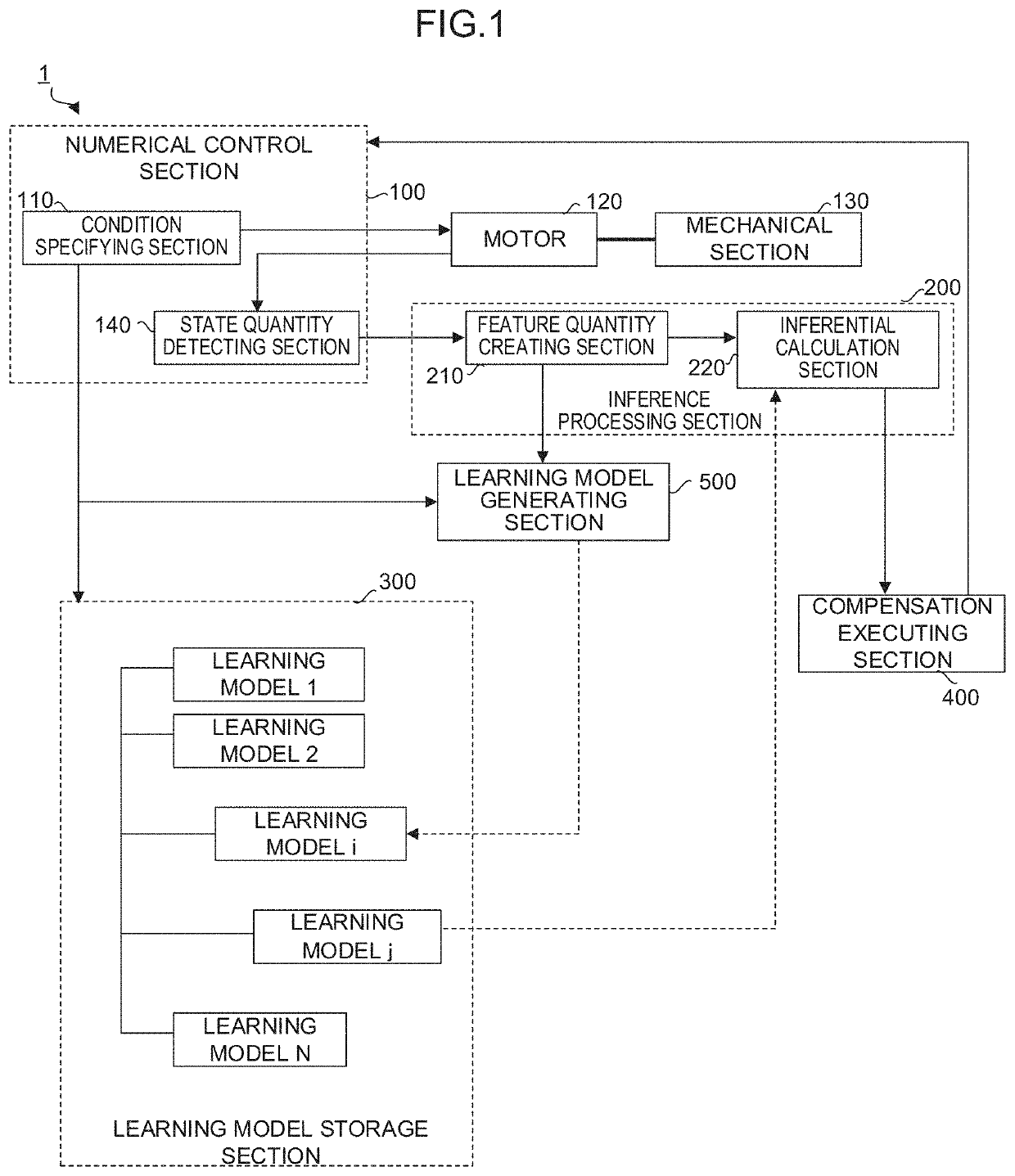
[0034]FIG. 1 is a schematic functional block diagram of a thermal displacement compensation system 1 according to a

[0035]The respective functional blocks shown in FIG. 1 are implemented as a processor such as a CPU or a GPU provided in a computer such as a numerical controller, a cell computer, a host computer, or a cloud server controls operations of various parts of an apparatus in accordance with each system program.

[0036]The thermal displacement compensation system 1 according to the present embodiment includes a numerical control section 100 as an edge device, an inference processing section 200, and a learning model storage section 300. The numerical control section 100 serves as at least an object of observation / inference of a state. The performs inference with respect to a state of the edge device. The learning model storage section 300 stores and manages a plurality of learning models. The thermal displacement compensation system 1 according to the present embodiment furthe...

second embodiment

[0054]FIG. 4 is a schematic functional block diagram of the thermal displacement compensation system 1 according to a

[0055]In the thermal displacement compensation system 1 according to the present embodiment, each functional block is mounted to a single numerical controller 2. By adopting such a configuration, the thermal displacement compensation system 1 according to the present embodiment infers a thermal displacement compensation amount of each axis of the machine controlled by the numerical control section 100 using a different learning model in accordance with individual difference of a machine controlled by the numerical controller 2, and performs a thermal displacement compensation of each axis of the machine based on a result of the inference. In addition, each learning model in accordance with a condition of individual difference of the machine controlled by the numerical control section 100 can be generated / updated by one numerical controller 2.

third embodiment

[0056]FIG. 5 is a schematic functional block diagram of the thermal displacement compensation system 1 according to a

[0057]In the thermal displacement compensation system 1 according to the present embodiment, the numerical control section 100, the inference processing section 200, and the compensation executing section 400 are mounted on the numerical controller 2, and the learning model storage section 300 and the learning model generating section 500 are mounted on a machine learning apparatus 3 connected to the numerical controller 2 via a standard interface or network. The machine learning apparatus 3 may be mounted on a cell computer, a host computer, a cloud server, or a database server. By adopting such a configuration, since inference processing using a learned model which is relatively light processing can be executed on the numerical controller 2 and generation / update processing of a learning model which is relatively heavy processing can be executed on the machine learni...


PUM


Abstract

A thermal displacement compensation system detects a state quantity indicating a state of a machine, infers a thermal displacement compensation amount of the machine from the detected state quantity, and performs a thermal displacement compensation of the machine based on the inferred thermal displacement compensation amount of the machine. The thermal displacement compensation system generates a learning model by machine learning that uses a feature quantity, and stores the generated learning model in association with a combination of specified conditions of individual difference of the machine.

Description

RELATED APPLICATIONS[0001]The present application claims priority of Japanese Patent Application No. 2017-194041, filed on Oct. 4, 2017, the disclosure of which is hereby incorporated by reference herein in its entirety.BACKGROUND OF THE INVENTION1. Field of the Invention[0002]The present invention relates to a thermal displacement compensation system and, particularly, to a thermal displacement compensation system which performs a compensation while switching learning models in accordance with individual difference of a machine in a factory.2. Description of the Related Art[0003]In a machine, since a feed screw and a spindle are driven by a motor, the feed screw and the spindle expand and a machine position changes due to heat generated by the motor, frictional heat created by a rotation of a bearing, and frictional heat in a contact portion between a ball screw and a ball nut of the feed screw. In addition, since a change in ambient temperature of the machine and the use of a cool...

Claims


Application Information

Patent Timeline
Patent Type & Authority Patents(United States)
IPC IPC(8): B23Q15/18B23Q11/00G05B19/404
CPCB23Q15/18B23Q11/0007G05B19/404B23Q2220/006G05B2219/49206G05B2219/49219
Inventor HADA, KEITAIIJIMA, KAZUNORI
Owner FANUC LTD
Learn More