Robotic gripper

a robotic and gripper technology, applied in the direction of gripping heads, manipulators, manufacturing tools, etc., can solve the problems of increasing manufacturing costs, increasing assembly time, and limiting the mechanical system proposed by u.s. pat. no. 8,973,958

Active Publication Date: 2022-04-26
AEOLUS ROBOTICS CORP LTD
View PDF8 Cites 2 Cited by
  • Summary
  • Abstract
  • Description
  • Claims
  • Application Information

AI Technical Summary

Benefits of technology

[0008]The instant disclosure relates to a robotic finger that is capable of performing both pinch and conforming grasp modes but is able to conform to objects in 3 dimensions. Because it may be made from a single piece of rubber, plastic, or other highly flexible material, it has a number of advantages over both existing linkage-driven and flexure-based under-actuated gripper fingers.
[0009]Because the robotic finger may be manufactured as a single part, both the manufacturing and assembly time costs are dramatically reduced. Manufacturing technologies like injection molding and hot-press molding can allow for the part to be mass-produced at relatively low cost.
[0010]Because the robotic finger may be comprised of a single piece of elastomeric material, it is inherently robust; it is physically resistant to bumps, vibrations, and shocks. Furthermore, the robotic finger is inherently waterproof—a growing requirement for marine robotic environments. In addition, the robotic gripper is easier to clean.
[0011]Most importantly, the robotic finger achieves both pinch and conforming grasp capability, while retaining all the advantages of flexural fingers. Because the geometry of the finger is designed with 6-axis forces and torques in mind, each of its joints can rotate in 3 dimensions and translate in 3 dimensions, albeit in a non-linear fashion. Similarly, each of its links can be considered as a rigid link in 3D space, depending on specific design parameters. This allows the finger to achieve both pinch and conforming grasp modes, much like existing linkage-driven under-actuated gripper designs. Additionally, it also allows the finger to achieve compliance in 3 dimensions, much like existing flexure-jointed under-actuated gripper designs.
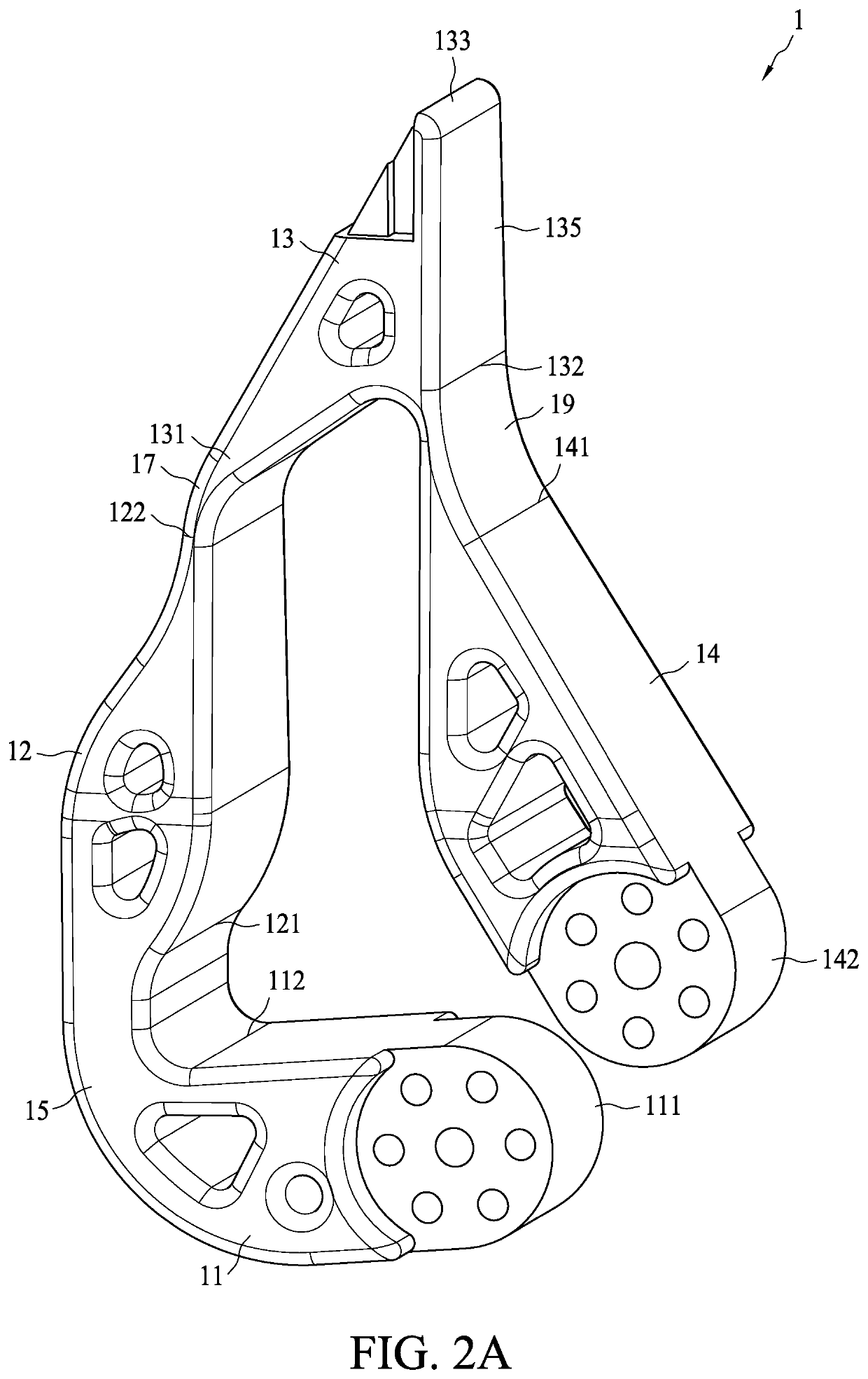
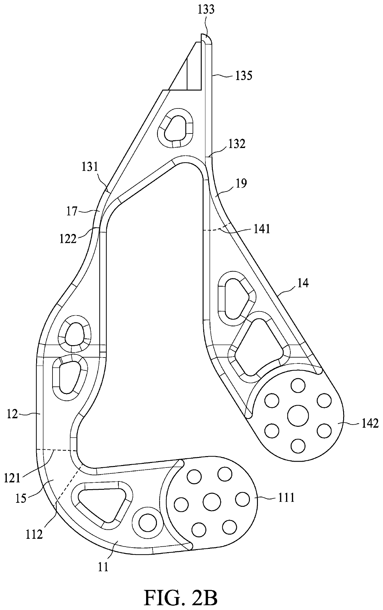
[0013]According to one exemplary embodiment of the instant disclosure, a robotic finger includes a first link having a first end and a second end, a second link having a first end and at least one second end, at least one third link having a first end and a second end, a fourth link having at least one first end and a second end, a first joint between the second end of the first link and the first end of the second link, at least one second joint between the second end of the second link and the first end of the third link, and at least one third joint between the second end of the third link and the first end of the fourth link. The first, second, third and fourth links and the first, second and third joints include elastic material and are formed in one piece. As described above, manufacturing the finger as a single part as benefits for manufacturability, cost, and waterproofing.
[0014]According to another exemplary embodiment of the instant disclosure, a robotic finger includes a first link having a first end and a second end, a second link having a first end and at least one second end, at least one third link having a first end and a second end, a fourth link having at least one first end and a second end, a first joint between the second end of the first link and the first end of the second link, at least one second joint between the second end of the second link and the first end of the third link, and at least one third joint between the second end of the third link and the first end of the fourth link. The first, second, third and fourth links and the first, second and third joints are configured to be compliant in three dimensions. As described above, three-dimensional compliance allows the gripper to grasp a wider variety of oddly-shaped objects, and improves robustness.

Problems solved by technology

However, the mechanical system proposed by U.S. Pat. No. 8,973,958 has its own limitations.
Yet, just like U.S. Pat. No. 8,973,958, existing ‘flexural’ gripper fingers have their own drawbacks.
They are generally cable-driven, increasing their assembly time.
They are generally in-molded, increasing manufacturing costs.
And most importantly, they only are able to achieve conforming grasp modes.
Because they do not have a ‘stable pinch region’, they cannot perform a true pinch grasp mode.

Method used


Image

  • Robotic gripper
  • Robotic gripper
  • Robotic gripper

Examples


Embodiment Construction

[0045]The aforementioned illustrations and following detailed descriptions are exemplary for the purpose of further explaining the scope of the instant disclosure. Other objectives and advantages related to the instant disclosure will be illustrated in the subsequent descriptions and appended drawings.

[0046]The following disclosure provides for many different embodiments, or examples, for implementing different features of the provided subject matter. Specific examples of components and arrangements are described below. These are, of course, merely examples and are not intended to be limiting. In the present disclosure, reference to the formation of a first feature over or on a second feature in the description that follows may include embodiments in which the first and second features are formed in direct contact, and may also include embodiments in which additional features may be formed between the first and second features, such that the first and second features may not be in d...


PUM


Abstract

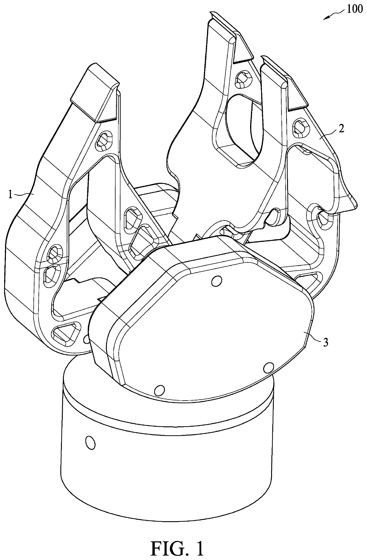
The present disclosure relates to a robotic gripper comprising a body and two robotic fingers mounted to the body. Each robotic finger includes a first link, a second link, a third link, a fourth link, a first joint, a second joint and a third joint. The first joint connects the first link and the second link, and the second joint connects the second link and the third link, and the third joint connects the third link and the fourth link. These links and these joints are comprised of elastic material and are formed in one piece.

Description

BACKGROUND1. Field of the Invention[0001]The instant disclosure relates to a fully-flexural robotic gripper, which can be configured to perform in pinch and conforming grasp modes.2. Description of Related Art[0002]Robotic grippers have been developed for various applications. Many grippers are designed for only one application—in other words, they may reliably grasp only specific classes of objects.[0003]For example, in one of various operation modes, the so-called ‘pinch grasp’ mode, one contact surface of a finger of a gripper may be configured to be substantially in parallel to another contact surface of another finger of the gripper. In this pinch mode, the parallel surfaces of each finger will contact the object to be manipulated or moved. Grippers operating in this pinch mode are especially capable at picking up relatively small or light objects, and rectangularly shaped objects.[0004]Another example of an operation mode is the conforming mode. In this mode, at least one fing...

Claims


Application Information

Patent Timeline
Patent Type & Authority Patents(United States)
IPC IPC(8): B25J15/12B25J15/10
CPCB25J15/12B25J15/103B25J15/106B25J15/022
Inventor ALBRIGHT, TUCKERPODNAR, GREGG
Owner AEOLUS ROBOTICS CORP LTD
Why Eureka
Try Eureka