
Waveguide transition between front and rear windows connected by a tapered plate to form upper and lower chambers that define an energy path through the transition

a transition and waveguide technology, applied in the direction of waveguide type devices, basic electric elements, coupling devices, etc., can solve the problems of inconvenient inability to realize high-integrated microwave circuits, and inability to reduce the cost of insertion loss of electromagnetic waves, so as to facilitate the realization of high-integrated microwave circuits and minimize the loss of electromagnetic waves. , the effect of easy separability

Active Publication Date: 2022-04-26
ELECTRONICS DESIGN & DEV CORP
View PDF5 Cites 0 Cited by
  • Summary
  • Abstract
  • Description
  • Claims
  • Application Information

AI Technical Summary

Benefits of technology

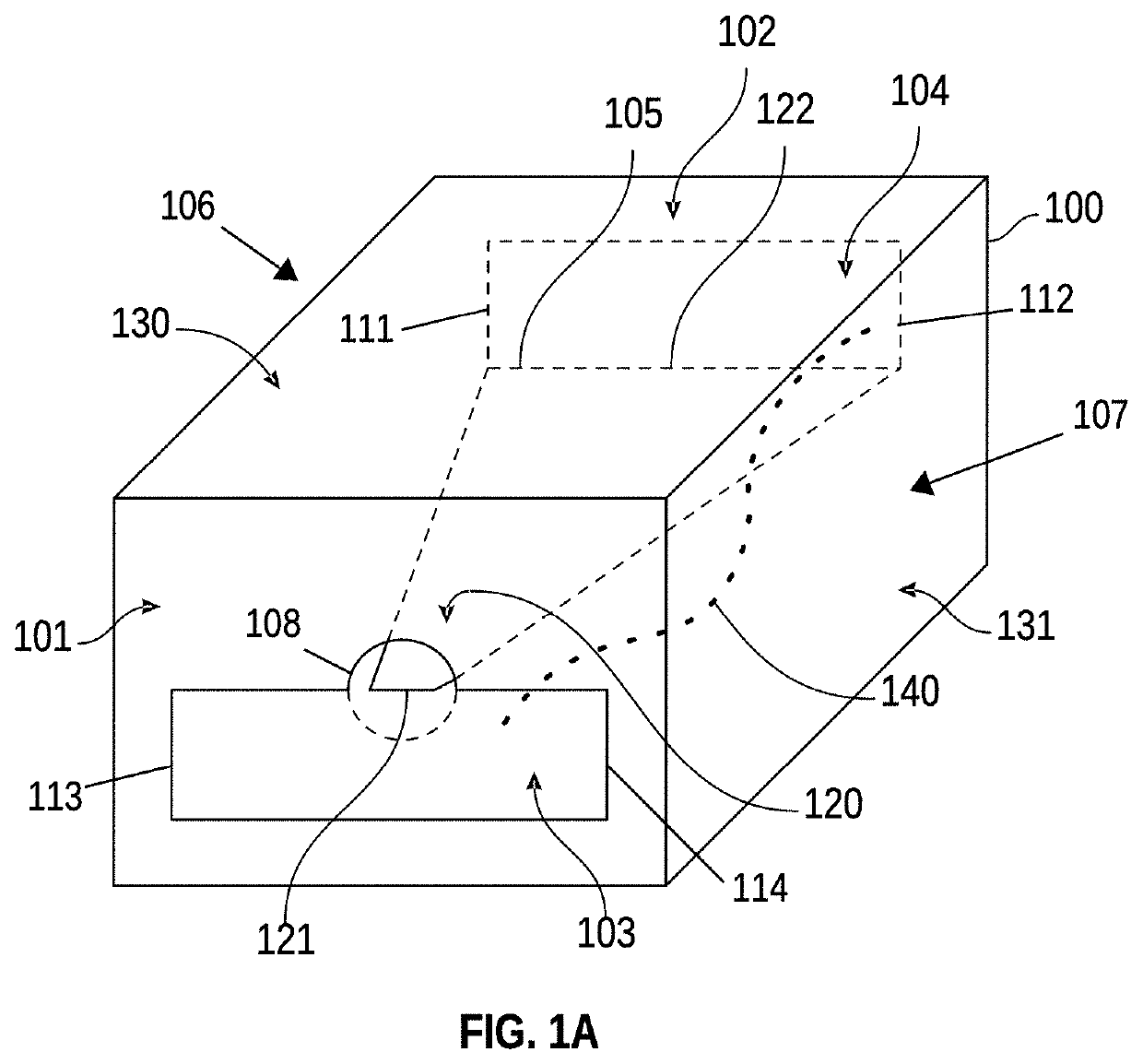
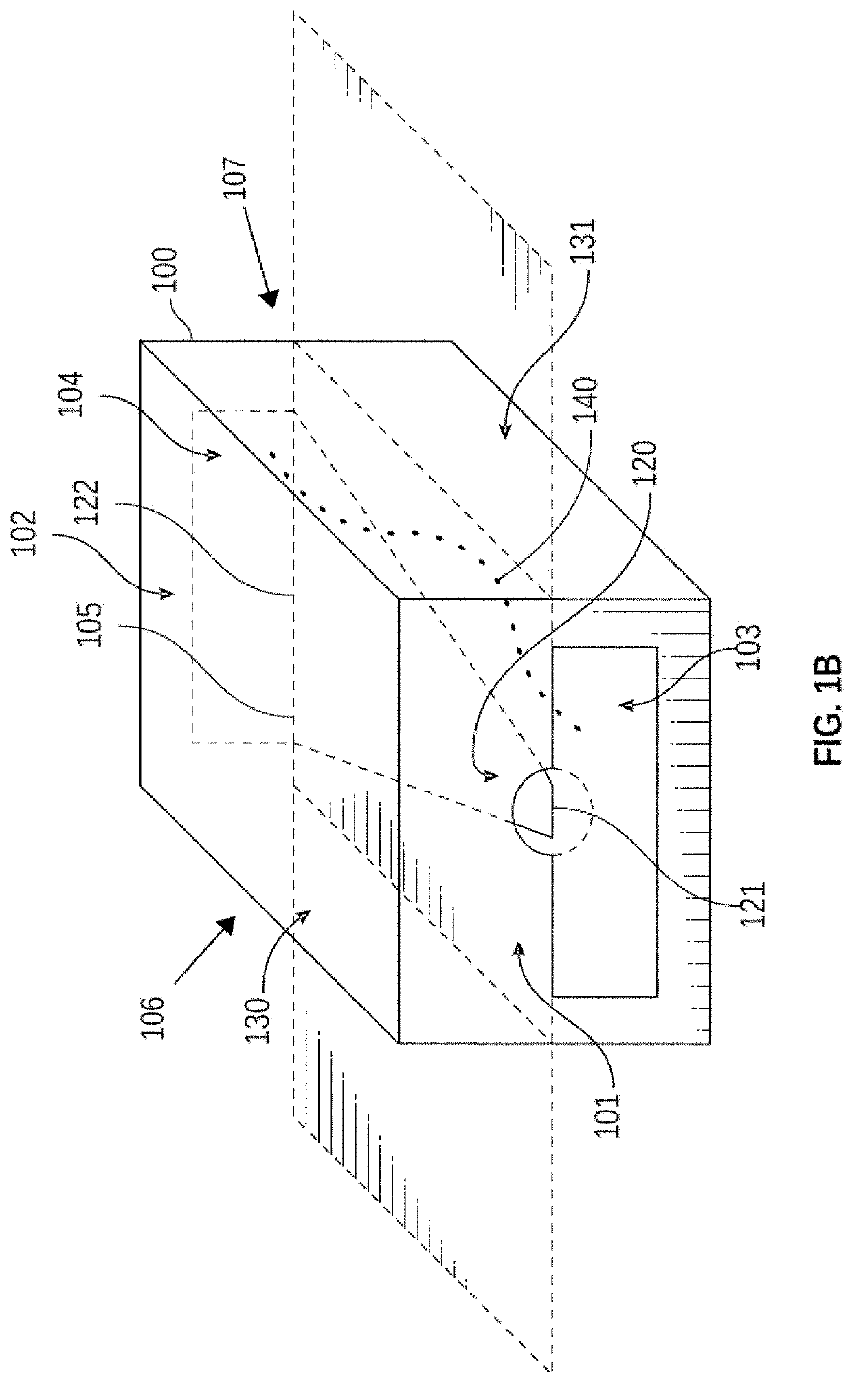
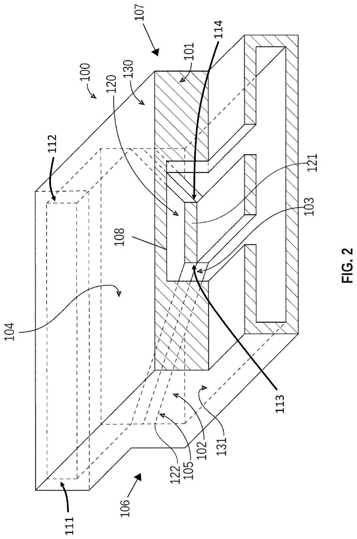
[0005]The waveguide transition of the present invention may mate a coplanar waveguide, which has both a center conductor and a grounded conductor, to a rectangular waveguide, which has a single conductor, through a common, electrically conducting coupling cavity that may act in conjunction with a tapered plate. The common coupling cavity may have two apertures through which to convey microwave electromagnetic radiation either from the coplanar waveguide to the rectangular waveguide, or vice versa. The tapered plate may join the two-conductor topology of the coplanar waveguide to the single-conductor topology of the rectangular waveguide so as to minimize insertion loss of electromagnetic wave power between the two apertures of the present invention. The coupling cavity and the tapered plate may exploit the full design discretion available to planar printed circuit design in the two dimensions, while imposing no extraordinary geometrical requirements in the third dimension of depth, which may make the coupling cavity and the tapered plate convenient for realizing highly integrated microwave circuits. The efficacy of the present invention may be measured by the metric of insertion loss, which may be the ratio of electromagnetic wave power incident upon the first aperture of the present invention, divided by the electromagnetic wave power propagated away from its second aperture.
[0006]One of the unique and inventive technical features of the present invention is that this waveguide transition may be both readily separable along the plane of the tapered plate, as well as readily fabricated in two separate planar printed circuit sub-assemblies. These sub-assemblies may be readily joined along the planes of respective tapered plates, and consequently the assembly may enjoy low insertion loss without requiring any calibration, tuning, intervening connectors or cabling. Without wishing to limit the invention to any theory or mechanism, it is believed that the technical feature of the present invention advantageously provides for unprecedented integration among coplanar waveguide and rectangular waveguide media in microwave circuits both within a single printed circuit board and among collections of printed circuit boards. This technical feature may make available complex microwave circuit designs that once may have been prohibitive in cost, complexity, area, and volume. None of the presently known prior art references or work has the unique inventive technical feature of the present invention. Furthermore, the prior art references teach away from the present invention. For example, prior art suggests that coplanar waveguide may be joined to rectangular waveguide by means of either a monopole radiator or a coupling loop, neither of whose constructions resembles the cross section of either coplanar waveguide or rectangular waveguide. Further, in the prior art, despite best design and manufacturing practices, each microwave circuit may require individual testing and tuning to achieve desired levels of performance. In the present invention, the tapered plate that may serve analogously to the monopole or loop may be realized in just two dimensions of planar design, by perforating the mating walls in the coplanar waveguide medium and the rectangular waveguide medium where the two media overlap. These same two dimensions of planar design may already be employed to control the critical conductor geometries, and hence the performance, of both the coplanar waveguide and rectangular waveguide. Therefore, the tapered plate may incur negligible incremental cost and complexity wherever it may be included. Furthermore, the inventive technical features of the present invention contributed to a surprising result. For example, the performance metric of insertion loss for the present invention may be found, by contrast with prior art, to require no tuning at all in order to meet required performance, further simplifying the waveguide transition design and improving its reliability over its operating life.

Problems solved by technology

This technical feature may make available complex microwave circuit designs that once may have been prohibitive in cost, complexity, area, and volume.
Further, in the prior art, despite best design and manufacturing practices, each microwave circuit may require individual testing and tuning to achieve desired levels of performance.
Therefore, the tapered plate may incur negligible incremental cost and complexity wherever it may be included.

Method used


Image

  • Waveguide transition between front and rear windows connected by a tapered plate to form upper and lower chambers that define an energy path through the transition
  • Waveguide transition between front and rear windows connected by a tapered plate to form upper and lower chambers that define an energy path through the transition
  • Waveguide transition between front and rear windows connected by a tapered plate to form upper and lower chambers that define an energy path through the transition

Examples


example

[0052]The following is a non-limiting example of the present invention. It is to be understood that the example is not intended to limit the present invention in any way. Equivalents or substitutes are within the scope of the present invention.

[0053]In one example embodiment, a 5G band pass filter implementation comprises two waveguide transition instances as described in the present invention. The example embodiment: is fabricated in a two conductor-layer planar printed circuit technology, wherein the structural dielectric material supporting the printed-circuit board lamina has an effective relative dielectric constant of about 3.0; operates at a center frequency of 28 gigahertz; and is available as a component for solder attachment to a host printed circuit board whose complementary footprint is specified by the product data sheet of this example embodiment. Its container (100): has the form of a rectangular prism; comprises a tapered plate (120) that tapers linearly from rear ed...


PUM


Abstract

The present invention features a waveguide transition. A waveguide transition is used to join two dissimilar segments of waveguide, in this case coplanar waveguide to rectangular waveguide, and vice-versa. Care taken during the design of the waveguide transition ensures that the reflection of electromagnetic waves, which may be traveling along the coplanar waveguide segment and toward the waveguide transition and subsequent rectangular waveguide segment, is minimized.

Description

CROSS-REFERENCES TO RELATED APPLICATIONS[0001]This application is a continuation-in-part and claims benefit of U.S. patent application Ser. No. 16 / 750,691, now abandoned, filed Jan. 23, 2020, which is a non-provisional and claims benefit of U.S. Patent Application No. 62 / 795,815, filed Jan. 23, 2019, the specification(s) of which is / are incorporated herein in their entirety by reference.BACKGROUND OF THE INVENTIONField of the Invention[0002]The present invention relates in general to linear passive microwave circuit element structures that mate one waveguiding medium to a second, dissimilar, waveguiding medium. In particular, the present invention discloses devices to mate rectangular waveguide to coplanar waveguide in a manner compatible with commonly available printed circuit board fabrication techniques.Description of Related Art Including Information Disclosed[0003]Various types of microwave media, which may be used for conveying microwave electromagnetic radiation within confin...

Claims


Application Information

Patent Timeline
Patent Type & Authority Patents(United States)
IPC IPC(8): H01P5/02H01P5/08H01P5/107H01P5/18
CPCH01P5/024H01P5/082H01P5/107H01P5/181H01P5/182
Inventor CARDONA, JR., SERGIO E.PATRICK, KEVIN W.
Owner ELECTRONICS DESIGN & DEV CORP
Learn More