

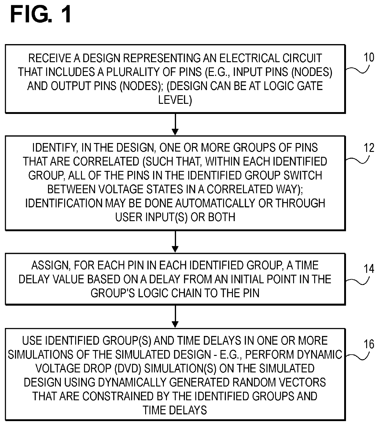
DVD analysis that accounts for delays
a delay analysis and delay technology, applied in the field of computer aided design and computer aided engineering, can solve the problems of power grids that deliver less than desired voltage levels, circuits that consume more power, and voltage levels that affect the operation of logic circuits, etc., to achieve accurate reflection of switching times in instances, limit switching activity, and constrain switching activity
- Summary
- Abstract
- Description
- Claims
- Application Information
AI Technical Summary
Benefits of technology
Problems solved by technology
Method used
Image

Examples
Embodiment Construction
[0021]Various embodiments and aspects will be described with reference to details discussed below, and the accompanying drawings will illustrate the various embodiments. The following description and drawings are illustrative and are not to be construed as limiting. Numerous specific details are described to provide a thorough understanding of various embodiments. However, in certain instances, well-known or conventional details are not described in order to provide a concise discussion of embodiments.
[0022]Reference in the specification to “one embodiment” or “an embodiment” means that a particular feature, structure, or characteristic described in conjunction with the embodiment can be included in at least one embodiment. The appearances of the phrase “in one embodiment” in various places in the specification do not necessarily all refer to the same embodiment. The processes depicted in the figures that follow are performed by processing logic that comprises hardware (e.g. circuit...
PUM
 Abstract
Description
Claims
Application Information