
Unidirectional ratchet wrench structure

a ratchet wrench and unidirectional technology, applied in the field of hand tools, can solve the problems of reducing the engagement efficiency of the pawl member and the ratchet, increasing the friction time of the ratchet, and not being able to be quickly detached,

Active Publication Date: 2022-05-10
ZHEJIANG MAXTOP TOOLS MFG CO LTD
View PDF6 Cites 0 Cited by
  • Summary
  • Abstract
  • Description
  • Claims
  • Application Information

AI Technical Summary

Benefits of technology

[0005]An objective of present invention is to provide a unidirectional ratchet wrench structure, which is capable of improving the above-mention problems.
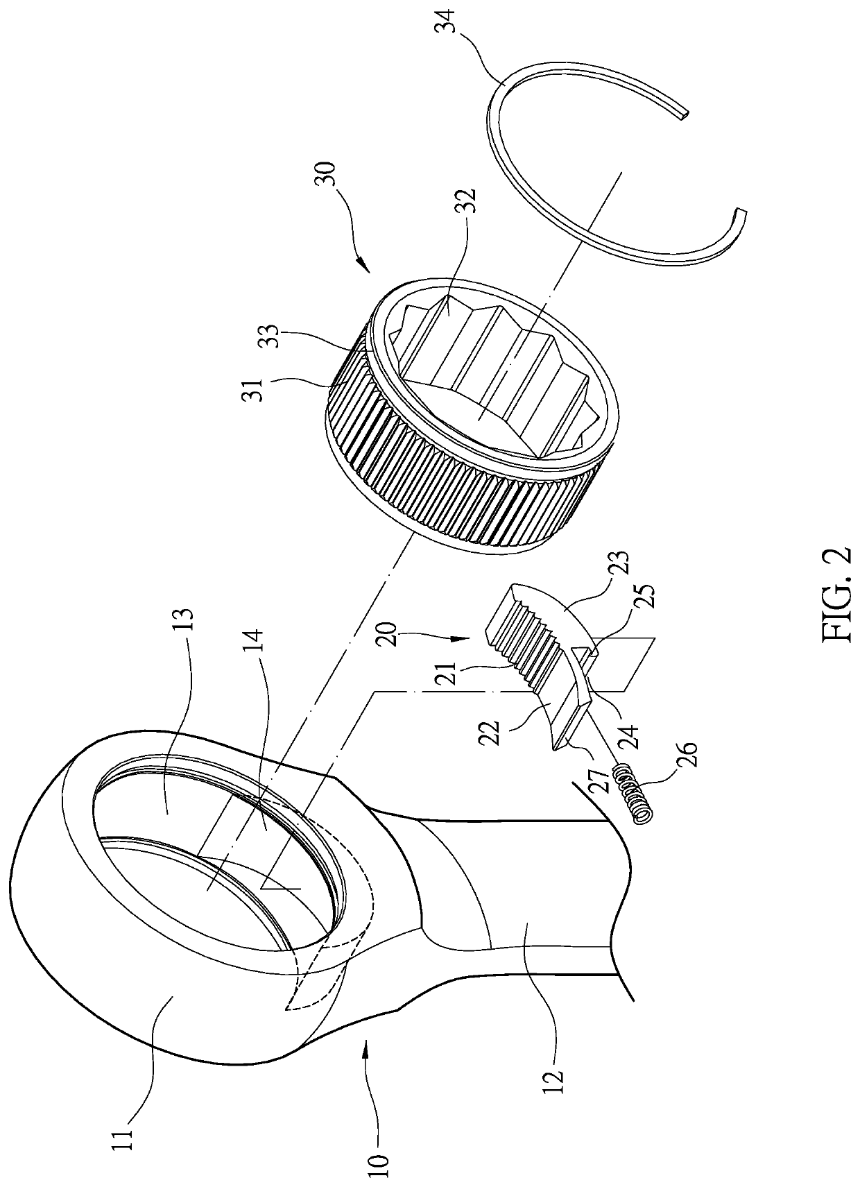
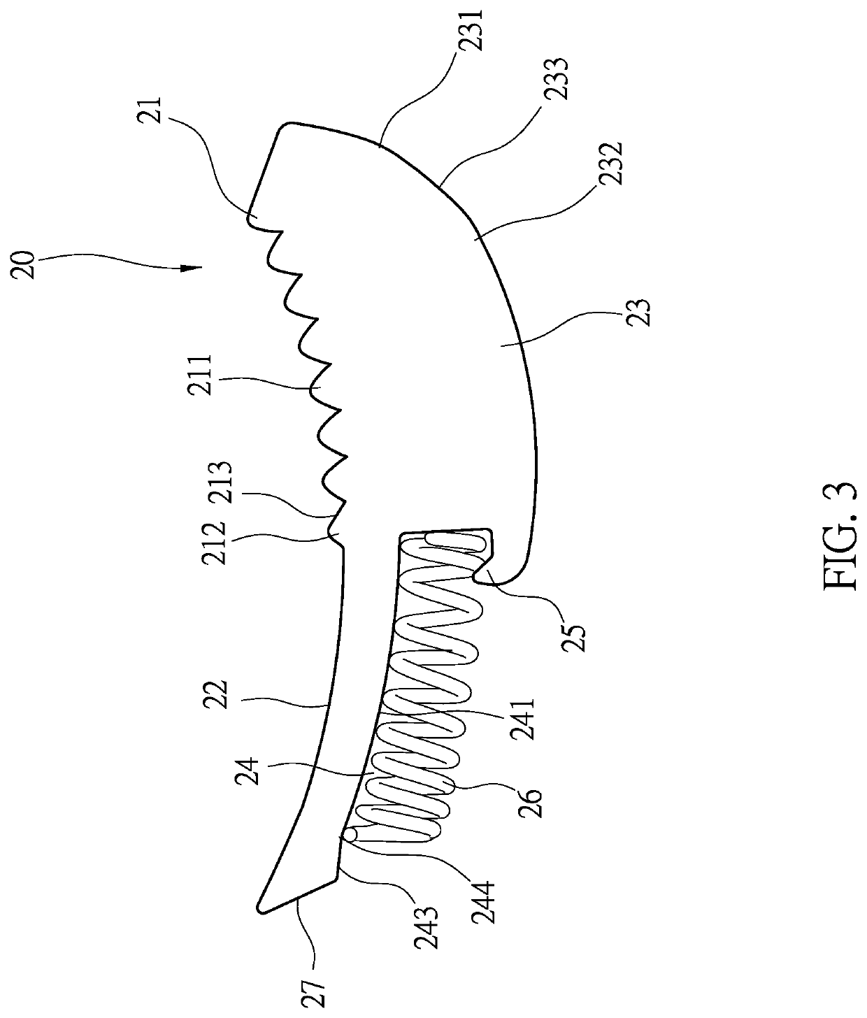
[0006]In order to achieve the above mentioned objective, a unidirectional ratchet wrench structure has a wrench member, a pawl and a ratchet. The wrench member has an accepting space for accommodating the ratchet and an accepting space for accommodating the pawl. A toothed section of the pawl has a plurality of equiangular teeth and an irregular tooth. Since the irregular tooth is lower than the height of the equiangular teeth, the irregular teeth irregular tooth is capable of quickly disengaging from the equiangular teeth of the ratchet. The arc section and the toothed section have different arc measures and not push against the outer periphery of the ratchet at the same time, through the abutment of the pivoting point and the change of the center of gravity of the pawl when the wrench is rotated, the pawl is capable of producing a seesaw yaw movement to achieves the effect of quick engagement and disengagement.

Problems solved by technology

Because the teeth angles of the pawl member are equal and the teeth of the outer periphery of the ratchet are engaged, when the pawl member and the ratchet want to separate and form an idling, the pawl member needs to be pushed for a longer stroke, which increases the friction time with the ratchets and cannot be quickly detached, thereby causing damage to the wear of the teeth of the pawl member.
In addition, the tooth and sliding surfaces of the pawl member simultaneously engage and push against the teeth on the outer periphery of the ratchet, and the spring is arranged at the central bottom of the pawl member facing the central position of the accepting groove, so that when the structure is used, the pawl member disengages or engages with the ratchet in a straight up and down manner, which greatly reduces the engage efficiency of the pawl member and the ratchet and causes collision between ratchet teeth.

Method used


Image

  • Unidirectional ratchet wrench structure
  • Unidirectional ratchet wrench structure
  • Unidirectional ratchet wrench structure

Examples


Embodiment Construction

[0019]First, please refer to FIGS. 1, 2 and 3. A unidirectional ratchet wrench structure comprises: a wrench member 10, a pawl 20 and a ratchet 30. The wrench member 10 has a head portion 11 and a handle portion 12. The head portion 11 comprises an accepting space 13 connected to an accepting groove 14 positioned toward the handle portion 12, and the accepting groove 14 has an arc shape. The pawl 20 is accepted in the accepting groove 14. The pawl 20 has a concave upper surface facing the accepting space 13 and comprises a toothed section 21 and an arc section 22. The toothed section 21 has a plurality of equiangular teeth 211 and an irregular tooth 212 adjacent to the arc section 22. An addendum angle of the irregular tooth 212 is greater than an addendum angle of the equiangular teeth 211, and there is a 10-20° difference between them. In addition, an addendum height of the irregular tooth 211 is lower than an addendum height of the equiangular teeth 211 which provides an escaping...


PUM


Abstract

A unidirectional ratchet wrench structure has a wrench member, a pawl and a ratchet. The wrench member has an accepting space for accommodating the ratchet and an accepting space for accommodating the pawl. A toothed section of the pawl has a plurality of equiangular teeth and an irregular tooth. Since the irregular tooth is lower than the height of the equiangular teeth, the irregular teeth irregular tooth is capable of quickly disengaging from the equiangular teeth of the ratchet. The arc section and the toothed section have different arc measures and not push against the outer periphery of the ratchet at the same time, through the abutment of the pivoting point and the change of the center of gravity of the pawl when the wrench is rotated, the pawl is capable of producing a seesaw yaw movement to achieves the effect of quick engagement and disengagement.

Description

BACKGROUND of INVENTIONField of Invention[0001]The present invention relates to a hand tool, and more particularly to a unidirectional ratchet wrench structure.Description of Related Art[0002]A conventional ratchet wrench, as in U.S. Pat. No. 7,444,903B1, Taiwan application publication No. M327769: a ratchet wrench has a wrench body, a ratchet wheel, a pawl member and an elastic member. The wrench body having an end portion provided with a mounting hole and a receiving chamber connected to the mounting hole. The ratchet wheel mounted in the mounting hole of the wrench body and having an outer wall provided with a plurality of ratchet teeth. The pawl member defining a top surface and a bottom surface mounted in the receiving chamber of the wrench body having a first side including a first end provided with a plurality of locking teeth extending from the top surface to the bottom surface engaged with the ratchet teeth of the ratchet wheel successively and completely and a second end p...

Claims


Application Information

Patent Timeline
Patent Type & Authority Patents(United States)
IPC IPC(8): B25B13/46
CPCB25B13/463B25B13/04
Inventor SHIH, NENG-CHIA
Owner ZHEJIANG MAXTOP TOOLS MFG CO LTD
Learn More