
Display system with variable resolution

a display system and variable resolution technology, applied in the field of matrix display devices, can solve the problems of device lack of precision and flexibility, too large data flow, and inability to achieve precision and flexibility,

Active Publication Date: 2022-05-17
COMMISSARIAT A LENERGIE ATOMIQUE ET AUX ENERGIES ALTERNATIVES
View PDF11 Cites 0 Cited by
  • Summary
  • Abstract
  • Description
  • Claims
  • Application Information

AI Technical Summary

Benefits of technology

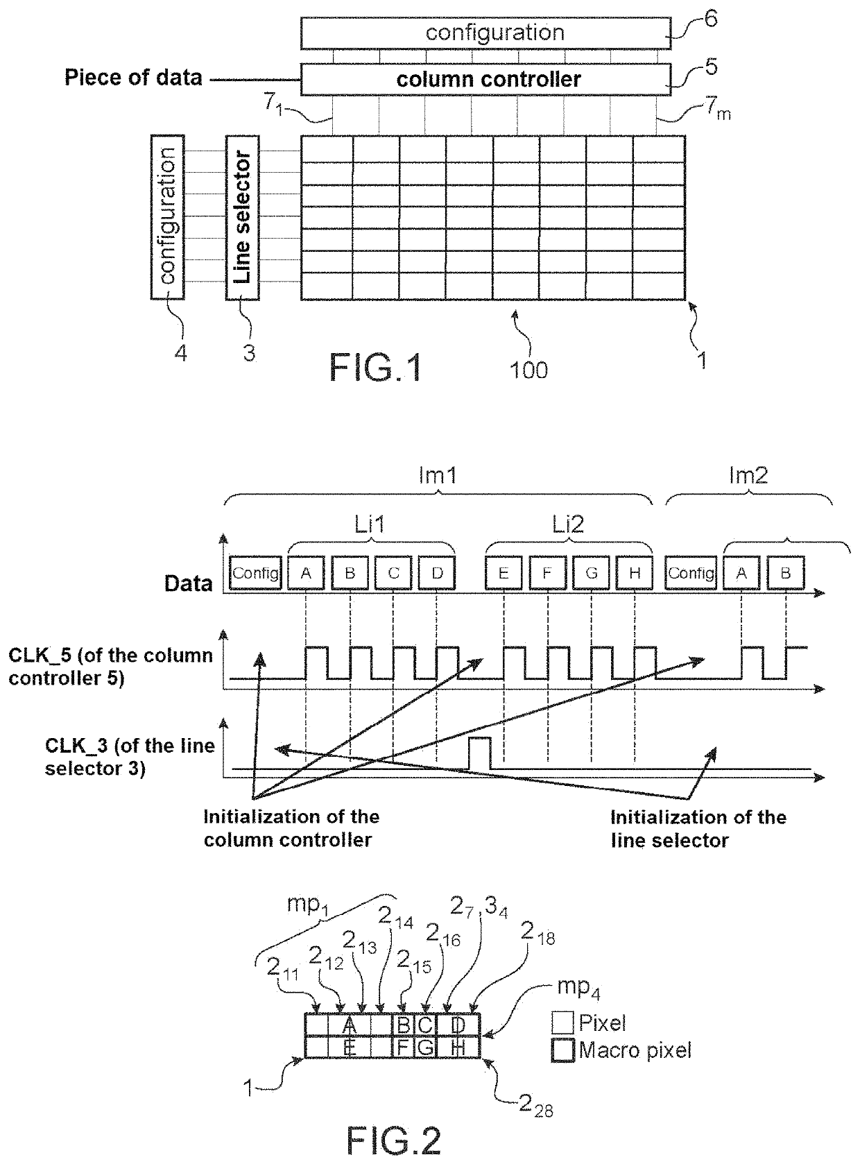
[0017]This duplication allows to form macropixels and to provide a reduction in the stream of pixel data presented at the input of the display device. A piece of data intended for a macropixel is presented once at the input of the display device and is automatically duplicated via this selection circuit by simultaneous selection of a plurality of lines and / or columns.

Problems solved by technology

However, for certain display devices or certain applications, a data flow that is too great can turn out to be disadvantageous, in particular because of the consumption involved in the management of this flow.
Such a device lacks a range of attainable resolutions as well as precision and flexibility with regard to the positioning of the zones with different resolutions with respect to each other.
The problem arises of finding a new display device which is improved with respect to the disadvantages mentioned above.

Method used


Image

  • Display system with variable resolution
  • Display system with variable resolution
  • Display system with variable resolution

Examples


Embodiment Construction

[0010]One embodiment of the present invention provides a device for displaying images comprising a matrix of pixels arranged by forming a plurality of lines and a plurality of columns of pixels, the display device comprising:[0011]is a line selector, coupled with the lines of the matrix of pixels,[0012]a column controller coupled with the columns of the matrix of pixels,

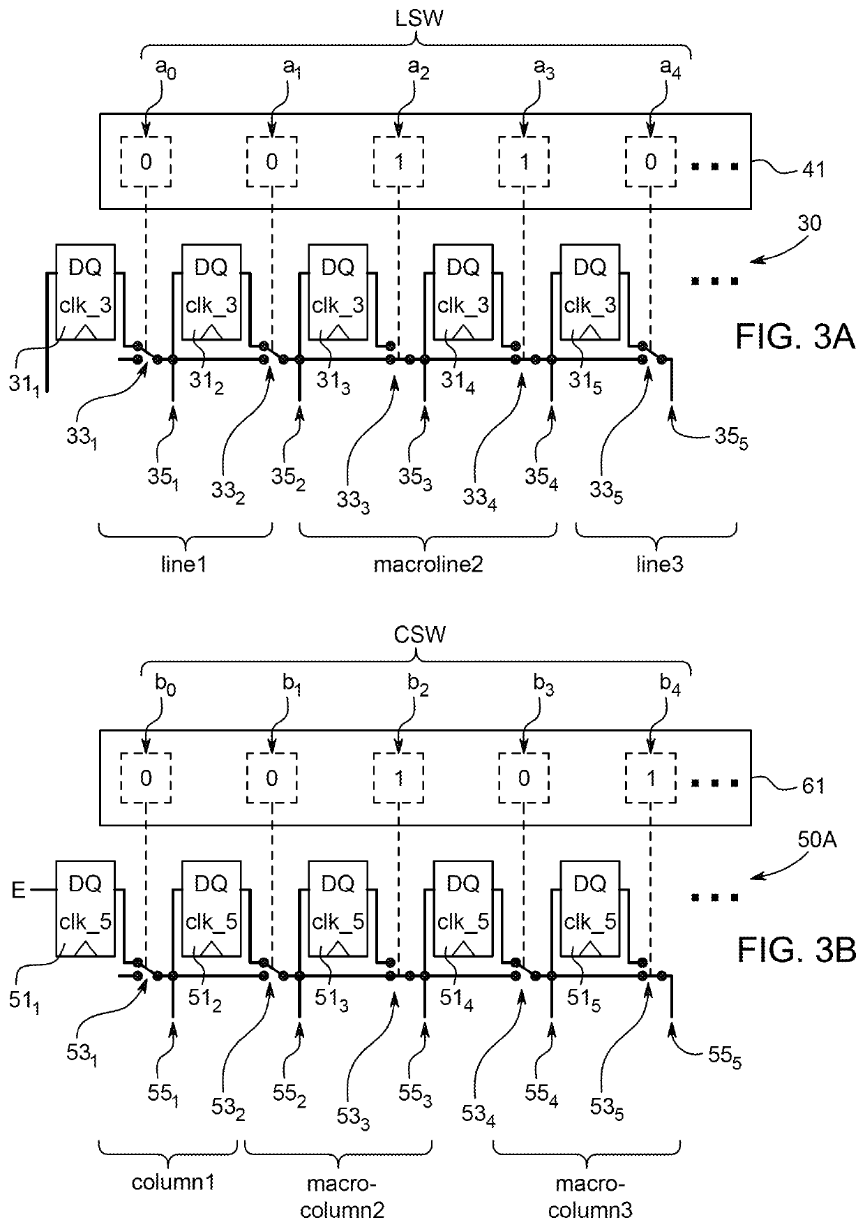
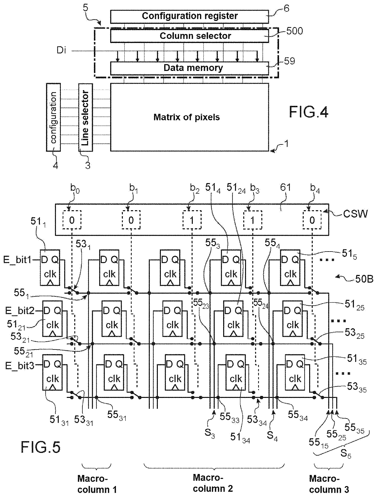
[0013]the line selector and / or the column controller comprising:[0014]a selection circuit including a succession of output channels corresponding to various rows of said matrix of pixels, said selection circuit further comprising a succession of shift registers and a succession of switches controlled by at least one configuration word, each shift register being associated with an output channel of said selection circuit and with a switch of said succession of switches, a given output channel of said selection circuit being capable of being connected to an input of a shift register following the shift register with wh...


PUM


Abstract

Device for displaying images comprising: a line selector, the line selector and / or the column controller comprising a selection circuit comprising a succession of output channels corresponding to various rows of the matrix, said selection circuit further comprising a succession of shift registers and a succession of switches controlled by at least one configuration word for controlling the respective configurations of the succession of switches of said selection circuit and for placing the switches of said succession of switches respectively in one of said first configuration or second configuration according to the respective states of configuration bits of this configuration word, the first configuration allowing to propagate a signal in the succession of registers, the second configuration allowing to duplicate a signal emitted on the preceding output channel on the given output channel in order to consequently duplicate on a row corresponding to the given output channel a piece of data intended for a row corresponding to the preceding output channel.

Description

TECHNICAL FIELD AND PRIOR ART[0001]The present invention relates to the field of matrix display devices, also called screens.[0002]In this field, it is generally sought to increase the resolution, the refresh rate, and the number of bits encoding a color displayed by each pixel, which requires transmitting to the screen a data flow that is more and more substantial.[0003]However, for certain display devices or certain applications, a data flow that is too great can turn out to be disadvantageous, in particular because of the consumption involved in the management of this flow.[0004]Conventional systems for compression of data implement an elimination of temporal redundancy in order to provide a compressed data stream to a display device. This is the case of the systems using for example an MPEG data flow. This type of encoding requires the use of a dedicated decoder, which can turn out to be itself a consumer of energy. This decoder generally constitutes a component distinct from th...

Claims


Application Information

Patent Timeline
Patent Type & Authority Patents(United States)
IPC IPC(8): G09G3/20G11C19/28
CPCG09G3/20G11C19/28G09G2300/0426G09G2310/0272G09G2310/0286G09G2340/04G09G2310/027G09G2310/0267G09G2340/0414G09G2340/0421
Inventor SEAUVE, YOANN
Owner COMMISSARIAT A LENERGIE ATOMIQUE ET AUX ENERGIES ALTERNATIVES
Learn More