Wheelchair lift-transfer device

a technology for wheelchairs and lifts, applied in medical science, nursing beds, ambulance services, etc., can solve the problems of affecting the lifting range, and affecting the mobility of wheelchairs

Active Publication Date: 2022-05-24
ADAPTIVE MOBILITY LLC
View PDF21 Cites 4 Cited by
  • Summary
  • Abstract
  • Description
  • Claims
  • Application Information

AI Technical Summary

Benefits of technology

[0014]1. A compact patient lift-transfer device with increased lifting range, including lifting a patient from lying on the floor to standing position yet have a retracted column height that will pass under a normal height table top.
[0015]2. A compact wheelchair lift-transfer device that improves transfer to and from conventional wheelchairs by providing a pair of independently adjustable rear wheel support arms that remain substantially parallel when they are adjusted, including a range of adjustment that allows a narrow position for passage of the pair of support arms under and between the wheels of a conventional wheelchair and a wide position that allows space for a chair to sit between the wheel support arms and / or provide improved stability for driving the wheelchair lift-transfer device with the lift elevated.
[0016]3. A compact rear entry wheelchair lift-transfer device that improves transfer to and from a bed including a semi-rigid seat plate that can be easily placed under a patient who is on a bed and be quickly attached to the lift.

Problems solved by technology

Conventional patient controlled powered wheelchairs are front entry in that the supporting structure is under and behind the seated user, and even though they provide great mobility, the conventional wheelchair is hampered by front entry when lifting and transfer capabilities are added.
There are numerous patient lift devices that have adequate lifting capability for certain situations; however those with lifting range sufficient to lift a patient from lying on the floor to standing height are not both compact and mobile.
There are ceiling mounted lifts with great lifting range but these are confined to a ceiling track or large frame structure.
There are jackscrew driven and hydraulic driven vertically guided lifts that have high lift ranges but these lifts have very tall guide support structures that increase their height and reduce their mobility.
This structure simplifies the lift mechanism but the structure resulting from this central location interferes with the patient's knees and also makes it difficult to locate the lifting point of the lift close enough to a patient that is lying on the floor.
U.S. Pat. No. 6,430,761 describes a Compact Portable Patient Lift that is intended to be portable but it has inadequate lifting range to lift a patient from lying on the floor to standing, it has an interfering central lifting support column and does not provide the capability for self-lifting or patient driving.
U.S. Pat. No. 4,719,655 describes a patient lift with two telescoping vertical guide columns but also has an interfering central lift mechanism and no means to adjust the width of the wheel support arms.
However, this device has very tall columns to achieve the high lift range and has no provision for patient operation of the lift.
However, this method requires a vertically hinged door to carry the raised wheelchair and most vehicle floors are too high for the illustrated seat lift to achieve an adequate height to clear the vehicle floor to allow entry and this method will not work when the vehicle door has a horizontal hinge axis like a van rear door.
However, this device achieves some of the capabilities of the present invention, but it has the long boom arm affect, the outwardly swinging wheel arm supports, and is too large for easy portability in a vehicle.
It also does not assist in raising the device itself to higher levels.
However, this is a front entry wheelchair with the lift motor, battery and cross shaft below the patient which eliminates the ability to move over a patient lying on the floor.
Also, this device has only a single jack screw in each lift column and the lift column height increases directly proportional to the lift stroke which makes the higher lift version too tall when retracted.

Method used


Image

  • Wheelchair lift-transfer device
  • Wheelchair lift-transfer device
  • Wheelchair lift-transfer device

Examples


Embodiment Construction

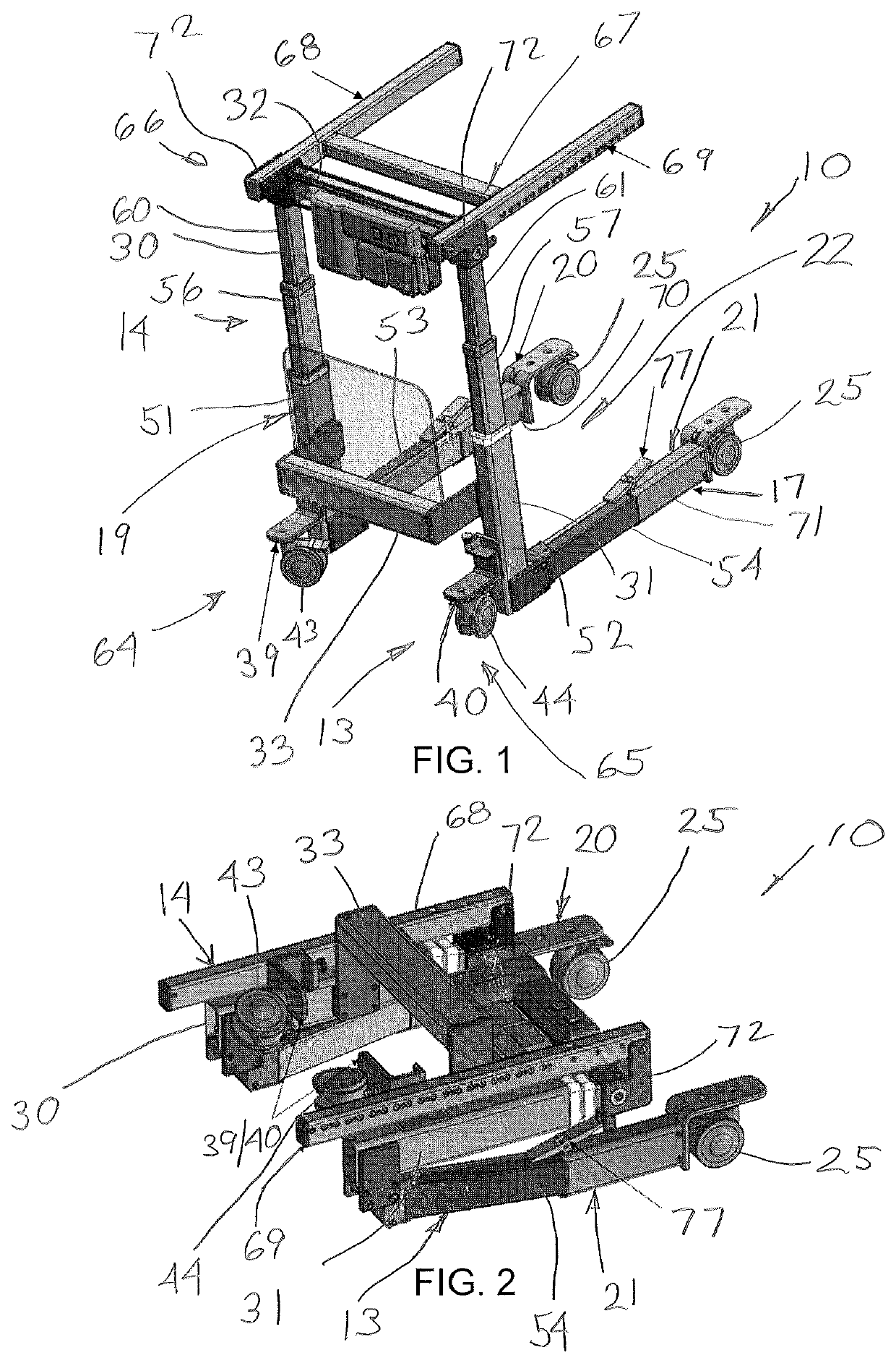
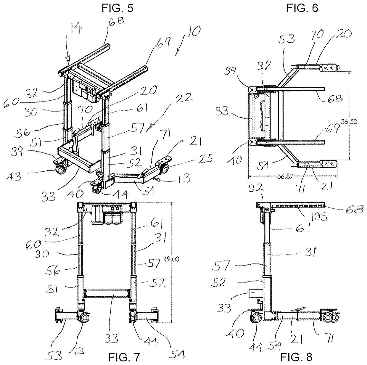
[0155]Referring to FIG. 1, there is illustrated one embodiment of the wheelchair lift-transfer device 10 (herein-after referred to as the “transporter” for convenience) configured as a rear entry power lift wheelchair. As seen in FIG. 2, the transporter 10 is readily foldable for storage or transport as will described herein.

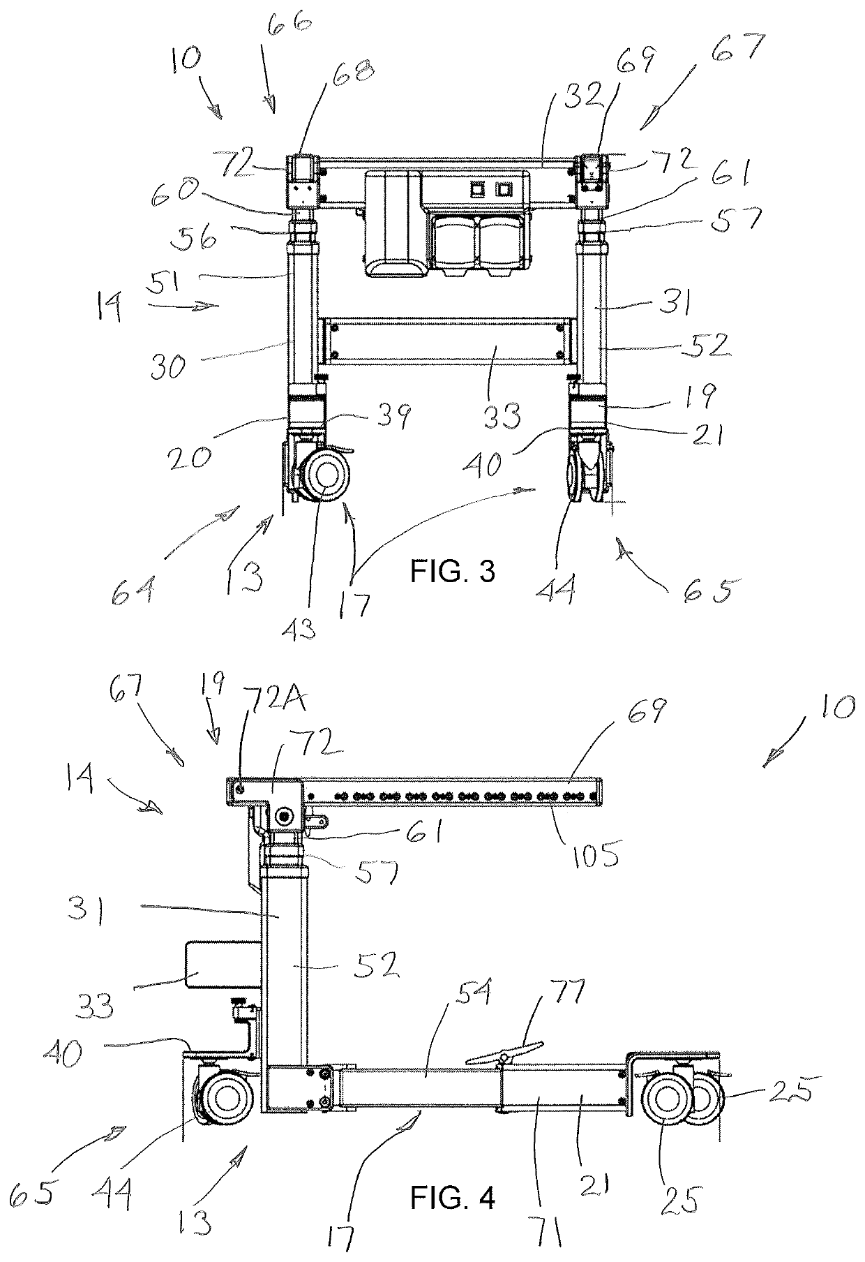
[0156]Referring to FIGS. 1 and 3-4, the transporter 10 includes a wheeled base assembly 13 having an upright assembly 14 projecting therefrom. The upright assembly 14 in turn mounts thereon a removable seat assembly 15 preferably comprising a seat support 16A and back support 16B (FIGS. 23 and 24), the latter being used for receiving an occupant / patient 18 for transporting by the transporter 10 and transfer to and from the transporter 10. The wheeled base assembly 13 includes a generally rigid and rearwardly-opening U-shaped horizontally extending wheeled base 17 that is defined by the upright assembly 14 at the front 19 and a pair of generally parallel and rear...


PUM


Abstract

An improved wheelchair lift-transfer device provides capabilities for a patient or caregiver to independently control the wheelchair and lift functions to elevate and move about safely. The compact lift-transfer device is readily usable to assist in transporting and lifting patients from various locations including wheelchairs, beds and chairs. Further, the lift-transfer device is also collapsible for storage and transport.

Description

CROSS REFERENCE TO RELATED APPLICATIONS[0001]This application is a continuation-in-part of co-pending PCT Application PCT / US2017 / 040723, filed Jul. 5, 2017, which PCT application in turn claims priority of U.S. Provisional Patent Application Ser. No. 62 / 358,249, filed Jul. 5, 2016, and U.S. Provisional Patent Application Ser. No. 62 / 428,798, filed Dec. 1, 2016, the disclosures of each application being incorporated herein by reference in their entirety.FIELD OF THE INVENTION[0002]This invention relates to an improved patient transfer-lift that is effective to transfer and lift patients.BACKGROUND OF THE INVENTION[0003]Generally as to the invention, many patients desire mobility and independence. Conventional patient controlled powered wheelchairs are front entry in that the supporting structure is under and behind the seated user, and even though they provide great mobility, the conventional wheelchair is hampered by front entry when lifting and transfer capabilities are added. Conv...

Claims


Application Information

Patent Timeline
Patent Type & Authority Patents(United States)
IPC IPC(8): A61G7/10
CPCA61G7/1046A61G7/1019A61G7/1025A61G7/1048A61G7/1051A61G7/1055A61G7/1057A61G7/1059A61G7/1074A61G2200/34A61G2200/36A61G5/085A61G7/1015
Inventor WILSON, HAROLD R
Owner ADAPTIVE MOBILITY LLC
Why Eureka
Try Eureka