Brake hydraulic pressure controller, motorcycle brake system, and manufacturing method of brake hydraulic pressure controller

a technology of brake hydraulic pressure controller and manufacturing method, which is applied in the direction of valve housing, braking system, transportation and packaging, etc., to achieve the effect of improving the manufacture efficiency strong demand and reducing the size of the brake hydraulic pressure controller

Active Publication Date: 2022-05-24
ROBERT BOSCH GMBH
View PDF33 Cites 0 Cited by
  • Summary
  • Abstract
  • Description
  • Claims
  • Application Information

AI Technical Summary

Benefits of technology

[0010]According to the brake hydraulic pressure controller according to the invention, the coil casing can be held by the base body by using the projected portion and the hole portion. Therefore, necessity of a fastening member such as a screw is reduced, manufacturability of the brake hydraulic pressure controller can be improved, and downsizing of the brake hydraulic pressure controller can be realized.
[0011]According to the motorcycle brake system according to the invention, with the above-described brake hydraulic pressure controller, a strong demand for downsizing of equipment mounted thereon can be handled.
[0012]According to the manufacturing method of the brake hydraulic pressure controller according to the invention, the coil casing can be held by the base body by using the projected portion and the hole portion. Therefore, the necessity of the fastening member such as the screw is reduced, and the manufacturability of the brake hydraulic pressure controller is improved.

Problems solved by technology

However, such a structure requires a process of attaching the fastening member and also requires a space for a tool used for the attachment of the fastening member.

Method used


Image

  • Brake hydraulic pressure controller, motorcycle brake system, and manufacturing method of brake hydraulic pressure controller
  • Brake hydraulic pressure controller, motorcycle brake system, and manufacturing method of brake hydraulic pressure controller
  • Brake hydraulic pressure controller, motorcycle brake system, and manufacturing method of brake hydraulic pressure controller

Examples


Embodiment Construction

[0021]A description will hereinafter be made on an embodiment of the invention with appropriate reference to the drawings.

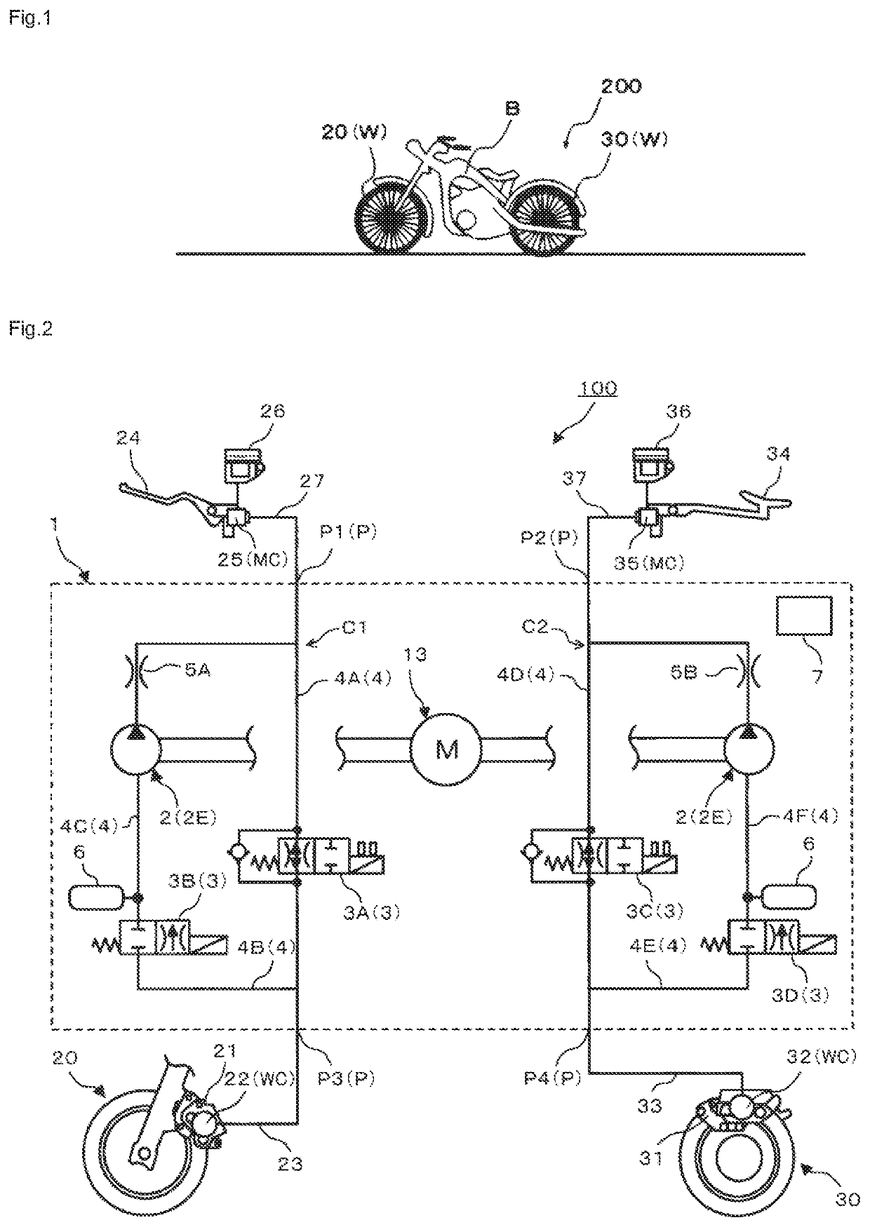
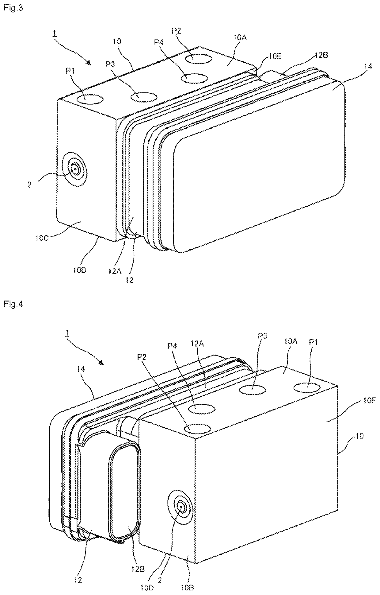
[0022]Note that a description will hereinafter be made on a case where a brake hydraulic pressure controller according to the invention is used for a motorcycle; however, the brake hydraulic pressure controller according to the invention may be used for a vehicle other than the motorcycle (for example, an automobile, a truck, or the like). In addition, a description will hereinafter be made on a case where the brake hydraulic pressure controller according to the invention is applied to a brake system that includes a front-wheel hydraulic circuit and a rear-wheel hydraulic circuit; however, the brake hydraulic pressure controller according to the invention may be applied to a brake system that only includes one of the front-wheel hydraulic circuit and the rear-wheel hydraulic circuit.

[0023]A configuration, an operation, and the like, which will be described below,...


PUM


Abstract

The invention has a purpose of obtaining a brake hydraulic pressure controller capable of attaching a coil casing to a base body with a simple configuration, a motorcycle brake system, and a manufacturing method of a brake hydraulic pressure controller.In the brake hydraulic pressure controller, at least one projected portion is provided in the coil casing, at least one hole portion is provided in a surface of the base body to which the coil casing is attached, the coil casing is attached to the base body in a state where the projected portion is inserted in the hole portion, the projected portion includes a hook portion that bulges in a direction to cross a projected direction of said projected portion, the coil casing is held by the base body when a part of the base body abuts a surface of a base-side region that is a region near a base of the projected portion with a top of a bulge of the hook portion being a reference.

Description

BACKGROUND OF THE INVENTION[0001]The invention relates to a brake hydraulic pressure controller, a motorcycle brake system that includes the brake hydraulic pressure controller, and a manufacturing method of a brake hydraulic pressure controller for manufacturing the brake hydraulic pressure controller.[0002]Conventionally, a brake system for a vehicle such as a motorcycle (a two-wheeled motor vehicle or a three-wheeled motor vehicle) can generate a braking force on a wheel when an occupant of the vehicle operates a brake lever, and a pressure of a brake fluid in a brake fluid circuit is increased. It has also been known to adopt an antilock brake system (ABS) unit, for example, as a brake hydraulic pressure controller that regulates the braking force.[0003]This brake hydraulic pressure controller can regulate the braking force to be generated on the wheel by increasing or decreasing the pressure of the brake fluid in the brake fluid circuit.[0004]As the brake hydraulic pressure con...

Claims


Application Information

Patent Timeline
Patent Type & Authority Patents(United States)
IPC IPC(8): F16K27/04B60T7/04B60T7/08B60T8/26B60T8/36
CPCF16K27/048B60T7/042B60T7/085B60T8/261B60T8/3685B60T8/3675B60T8/368
Inventor SAGAYAMA, KOSAKU
Owner ROBERT BOSCH GMBH
Why Eureka
Try Eureka