Test method and manufacturing method for electrical storage device

Active Publication Date: 2022-05-24
TOYOTA JIDOSHA KK
View PDF5 Cites 0 Cited by
  • Summary
  • Abstract
  • Description
  • Claims
  • Application Information

AI Technical Summary

Benefits of technology

The patent is about a method for quickly and accurately testing the condition of an electrical storage device, regardless of any disturbances. The method involves performing two phases of testing. In the first phase, the device is first energized with a high voltage to facilitate the convergence of circuit current. If a certain transition condition is satisfied, the process then moves into the second phase, where the voltage of the power supply is decreased to make the circuit current more stable and less prone to fluctuations. This method allows for a highly accurate determination of the device's condition, based on the stable current value in the second phase. Overall, this method provides a fast and effective way to test and manufacture electrical storage devices.

Problems solved by technology

However, the above-described existing technique has the following inconvenience.
Of course, reducing the parasitic resistance actually means increasing the voltage value of the external power supply.
However, if the resultant parasitic resistance is too close to zero, the stability of the circuit current deteriorates.
On the other hand, a small effective resistance value of the circuit means that the circuit current is sensitive to a disturbance and easily fluctuates.
The fact that the circuit current is far from the others in the group means that only that electrical storage device receives some sort of disturbance and fluctuations in the circuit current may increase later.
Alternatively, the electrical storage device may be a defective product.
The fact that the circuit current is far from the others in the group significantly means that the electrical storage device may be a defective product.

Method used


Image

  • Test method and manufacturing method for electrical storage device
  • Test method and manufacturing method for electrical storage device
  • Test method and manufacturing method for electrical storage device

Examples


Embodiment Construction

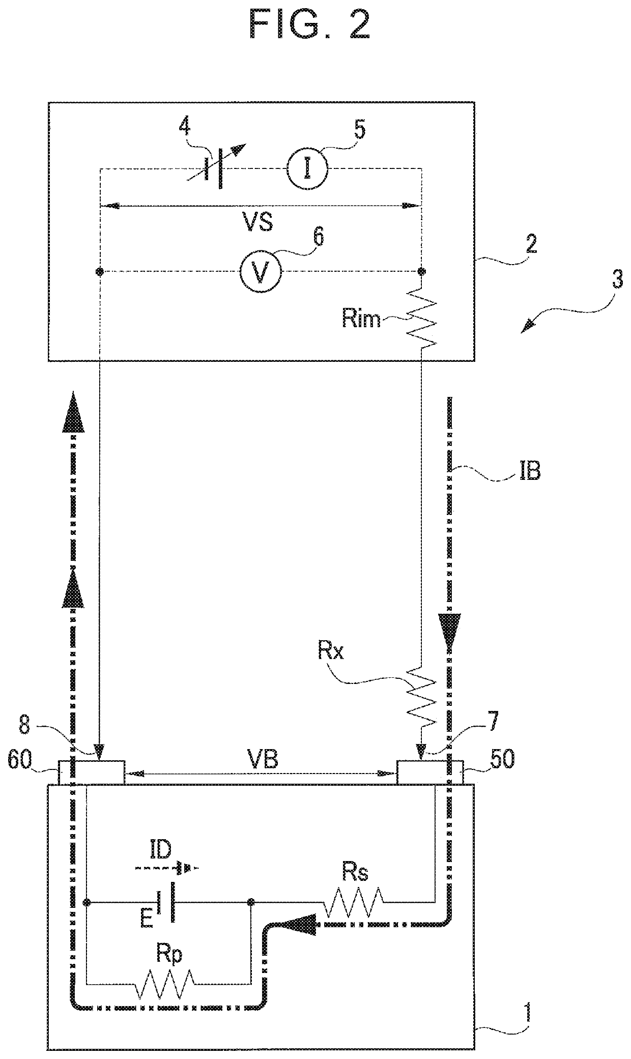
[0025]Hereinafter, an example embodiment of the disclosure will be described in detail with reference to the accompanying drawings. As shown in FIG. 2, a test method for an electrical storage device according to the present embodiment is performed in a state where a circuit 3 is assembled by connecting a measuring device 2 to a secondary battery 1 that is an electrical storage device to be tested. First, the basic principle of the test method for the secondary battery 1 with the measuring device 2 will be described.

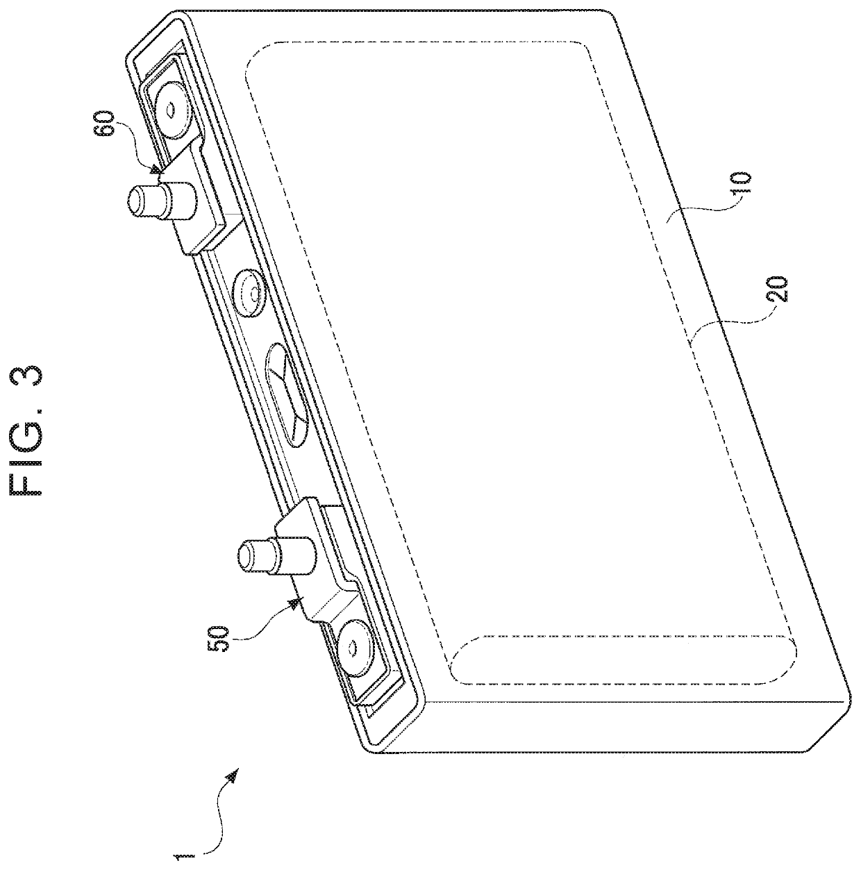
[0026]Although the secondary battery 1 is schematically shown in FIG. 2, the secondary battery 1 actually has a flat square appearance as shown in, for example, FIG. 3. The secondary battery 1 of FIG. 3 is made by accommodating an electrode stack 20 in an outer case 10. The electrode stack 20 is made such that a positive plate and a negative plate are stacked via a separator. An electrolyte is also accommodated inside the outer case 10 in addition to the electrode stack 2...


PUM


Abstract

By a first energization process of applying a voltage with the power supply to cause a current for charging the electrical storage device to flow through the circuit and a second energization process of, when a transition condition is satisfied during the first energization process, decreasing the voltage of the power supply to cause the current to further flow, a condition of an electrical storage is determined. An effective resistance value of the circuit is set to 0.1Ω or below. A decrease in the voltage of the power supply in transition from the first energization process to the second energization process is set such that the effective resistance value in the second energization process is an intermediate value between a parasitic resistance value of the circuit and the effective resistance value in the first energization process.

Description

INCORPORATION BY REFERENCE[0001]The disclosure of Japanese Patent Application No. 2019-219699 filed on Dec. 4, 2019 including the specification, drawings and abstract is incorporated herein by reference in its entirety.BACKGROUND1. Technical Field[0002]The disclosure relates to a test method for determining a condition of an electrical storage device. More specifically, the disclosure relates to a test method for an electrical storage device, which is capable of quickly determining a condition of an electrical storage device based on an amount of discharge current, other than a decrease in voltage, of the electrical storage device. The disclosure also relates to a manufacturing method for an electrical storage device, which includes the test method for an electrical storage device as part of a process.2. Description of Related Art[0003]Various test methods have been suggested to determine the conditions of secondary batteries and other electrical storage devices so far. Japanese Une...

Claims


Application Information

Patent Timeline
IPC IPC(8): G01R31/00G01R31/385G01R31/367H01M4/04H01M10/48G01R31/374
CPCG01R31/3865G01R31/367G01R31/374H01M4/0447H01M10/482G01R31/388G01R31/389G01R31/392Y02E60/10Y02P70/50H01M10/48H01M10/446
Inventor MATSUYAMA, YOSHIOTANAKA, RURIKOBAYASHI, KIWAMU
Owner TOYOTA JIDOSHA KK
Why Eureka
Try Eureka