Optical disc device

a technology of optical discs and optical discs, applied in the direction of digital signal error detection/correction, instruments, recording signal processing, etc., can solve the problem of inability to achieve stable reproduction, and achieve the effect of reducing the possibility of servo control becoming out of order and simple structur

Inactive Publication Date: 2010-11-25
FUNAI ELECTRIC CO LTD
View PDF5 Cites 2 Cited by
  • Summary
  • Abstract
  • Description
  • Claims
  • Application Information

AI Technical Summary

Benefits of technology

[0021]In view of the above described problem, it is an object of the present invention to provide an optical disc device in that out of order of the servo control is hardly caused when change of setting is achieved to perform correction of the spherical aberration.
[0023]According to this structure, it is possible to prevent influence of disturbance which is caused in the servo tracking system by the vibration accompanied by driving of the lens moving portion. That is, according to the structure, when correction of the spherical aberration is performed by making positional adjustment in direction of the light axis of the movable lens, possibility of occurrence that servo control becomes out of order can be reduced. In the structure, when the lens moving portion is driven, as an exceptional measure, gain of servo loop in the tracking servo system is made temporarily large. Because possibility of occurrence of oscillation of the tracking servo is reduced by appropriately selecting level of factor to make the gain of servo loop large, the above described effect can be obtained.
[0025]When the object lens is formed by resin, for example, because amount of the spherical aberration becomes easily fluctuated by change of environmental temperature, there may be a case where need for performing correction of the spherical aberration by driving of the lens moving portion is generated while the optical disc device is reproduced. Because the optical disc device having this structure can cope with this kind of fluctuation of the spherical aberration, in addition, even when the optical disc device copes with fluctuation of the spherical aberration as above described, it can reduce possibility of the servo control becomes out of order, a useful optical disc device can be provided.
[0026]It is preferable that in the optical disc device structured as above, the movable lens is a collimator lens. With this structure, a useful optical disc device can be realized by simple structure.
[0027]According to the optical disc device of the present invention, possibility of the servo control becomes out of order can be reduced when setting for correction of the spherical aberration is changed. As a result of this, it is possible to reduce situation where the time until the reproduction of the optical disc becomes longer than the necessity, situation where stable reproduction cannot be performed due to out of the servo control while the disc is reproduced, or the like.

Problems solved by technology

Further, if the servo control is made out of order by the above described reason as a result that the spherical aberration correction mechanism is driven to achieve correction of the spherical aberration while reproducing is performed, it causes a problem that stable reproduction cannot be attained.

Method used


Image

  • Optical disc device
  • Optical disc device
  • Optical disc device

Examples


Embodiment Construction

[0038]Hereinafter, an embodiment of the optical disc device according to the present invention will be explained in detail with reference to drawings.

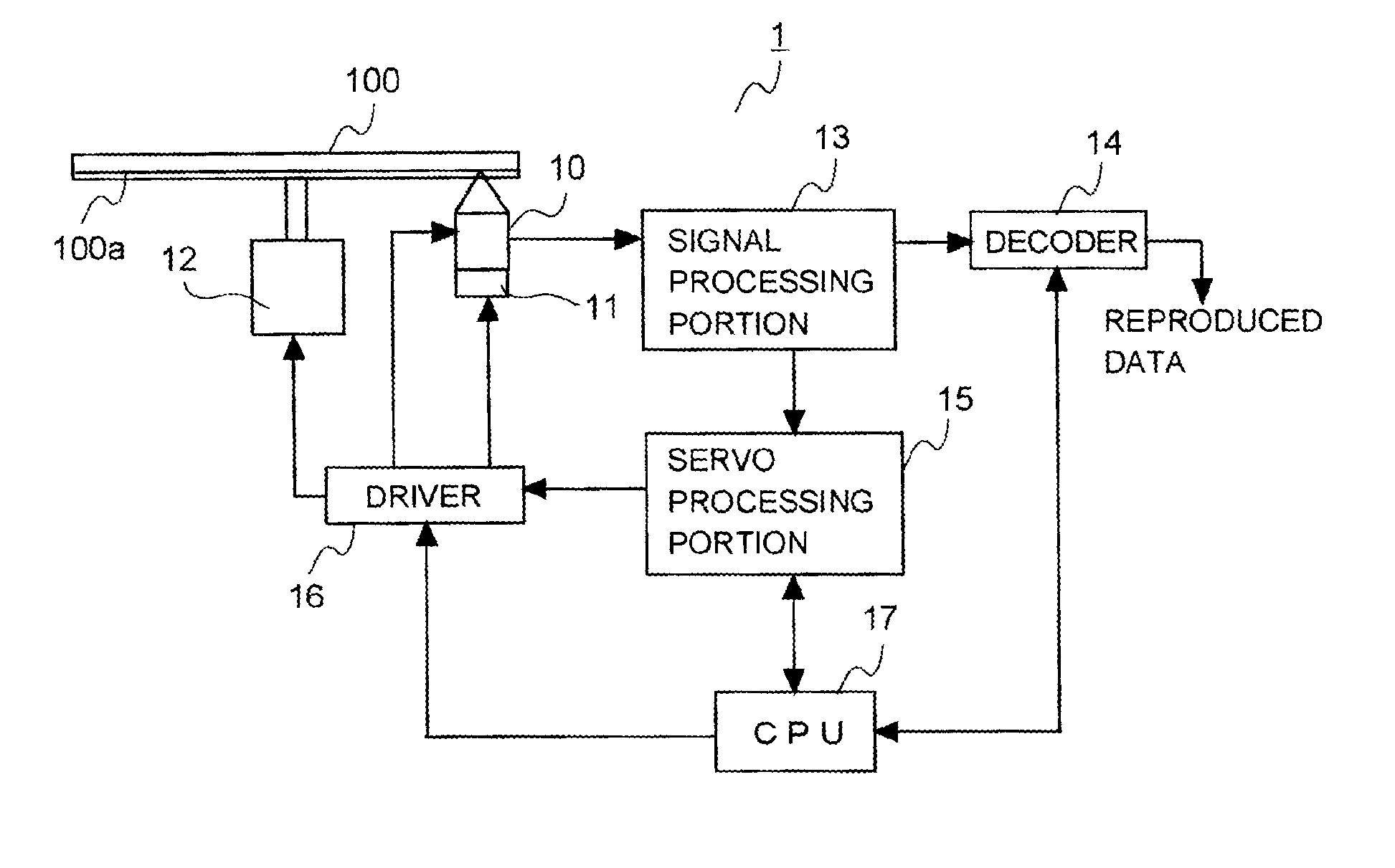
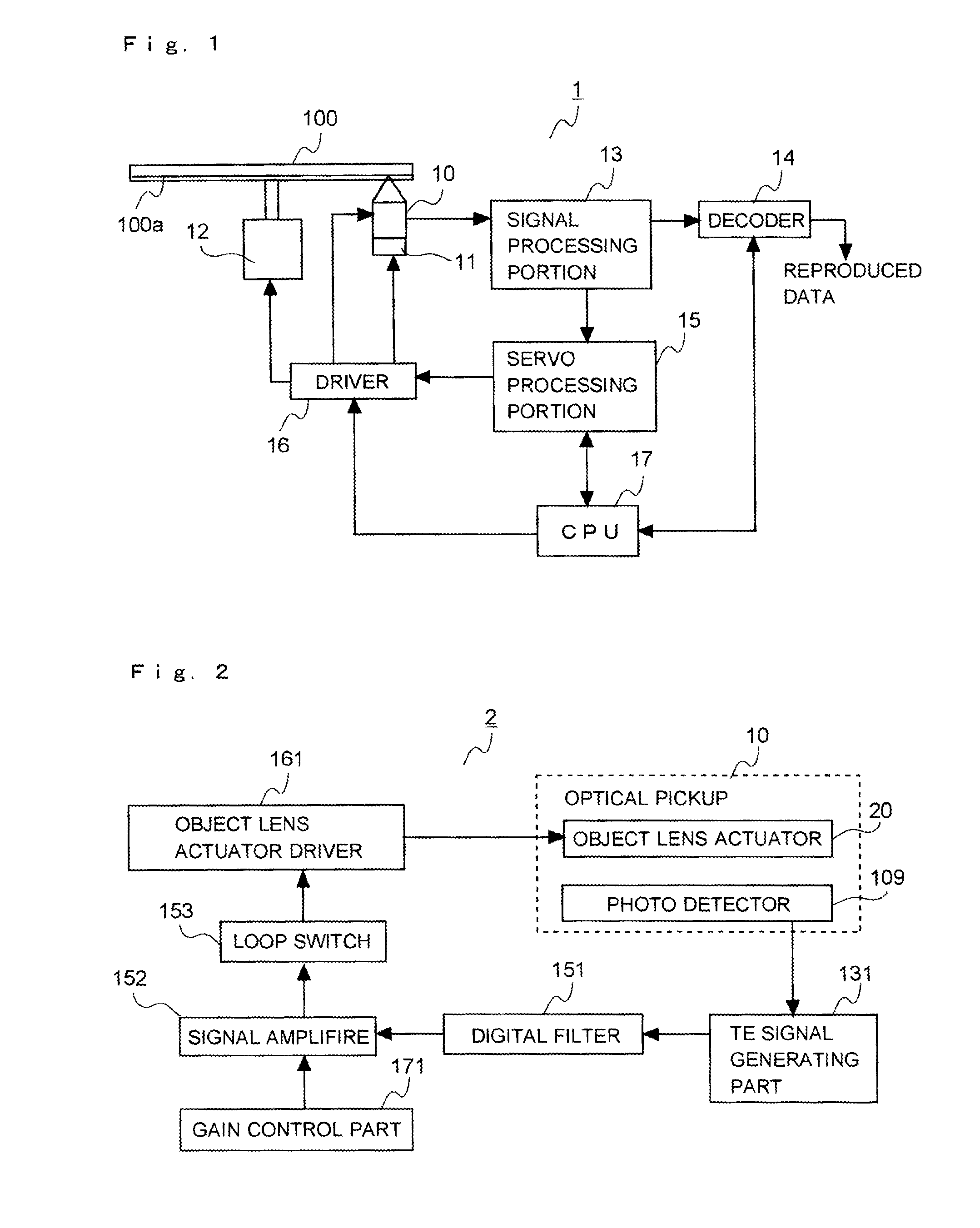
[0039]FIG. 1 is a block diagram to show structure of an optical disc device according to one embodiment of the present invention. As shown in FIG. 1, the optical disc device 1 according to the present embodiment includes an optical pickup 10, a sled motor 11, a spindle motor 12, a signal processing portion 13, a decoder 14, a servo processing portion 15, a driver 16 and a CPU (Central Processing Unit) 17.

[0040]The optical pickup 10 is a device to enables reading of information recorded on an optical disc 100. Structure of it is the same as the conventional optical pickup shown in FIG. 9. Therefore, explanation about structure of the optical pickup 10 is omitted here. Further, because structure of the optical pickup according to the present embodiment and that of the conventional optical pickup are the same, same reference numerals are ...


PUM

PropertyMeasurementUnit
temperatureaaaaaaaaaa
structureaaaaaaaaaa
biasing forceaaaaaaaaaa

Abstract

An optical disc device including: a light source; an object lens to focus light emitted from the light source on an information recording surface of an optical disc; a movable lens that is arranged on an optical path between the light source and the objective lens and arranged such that position thereof is adjustable along a direction of a light axis; a lens moving portion to move the movable lens along the direction of the light axis; a tracking servo system which makes a beam spot that is formed of the light from the light source through focusing by the objective lens keep on track of the optical disc; and a control part which controls gain of a servo loop of the tracking servo system is made temporarily larger when the movable lens is moved by the lens moving portion in comparison with a case where moving of the movable lens by the lens moving portion is not performed.

Description

[0001]This application is based on Japanese Patent Application No. 2009-122781 filed on May 21, 2009, and the contents of which are hereby incorporated by reference.BACKGROUND OF THE INVENTION[0002]1. Field of the Invention[0003]The present invention relates to an optical disc device which is used when reproduction of information recorded in an optical disc is performed, or recording of information in an optical disc is performed.[0004]2. Description of Related Art[0005]From the past, in an optical pickup provided in an optical disc device, there are some optical pickup including a spherical aberration correction mechanism in order to perform correction of the spherical aberration (for example, see patent documents 1 to 4).[0006]FIG. 9 is a schematic diagram to show an example of structure of a conventional optical pickup including a spherical aberration correction mechanism. In the conventional optical pickup 10, laser light emitted from a light source 101 is divided by a diffracti...

Claims


Application Information

Patent Timeline
Patent Type & Authority Applications(United States)
IPC IPC(8): G11B20/00G11B7/00
CPCG11B7/0901G11B7/0903G11B7/13927G11B7/0946G11B7/0941
Inventor NARITA, MAI
Owner FUNAI ELECTRIC CO LTD
Why Eureka
Try Eureka