Pseudo static memory device

a memory device and pseudo-static technology, applied in static storage, information storage, digital storage, etc., can solve the problem that the above-mentioned mechanism of adjustable accessing latency cannot be applied to the architecture of a single dynamic random access memory, and achieve the effect of improving the performance of the pseudo-static memory device and adjusting the accessing latency of the memory

Active Publication Date: 2022-06-14
WINBOND ELECTRONICS CORP
View PDF3 Cites 0 Cited by
  • Summary
  • Abstract
  • Description
  • Claims
  • Application Information

AI Technical Summary

Benefits of technology

[0006]The disclosure provides a pseudo static memory device that is capable of dynamically adjusting a memory accessing latency and improving use efficiency.
[0008]Based on the above, the pseudo static memory device of the present embodiment of the disclosure decides whether a collision of time occurs in at least one of the memories during self-refresh operation when the memory device is performing an accessing operation, and dynamically adjusts the accessing latency of the memory according to the decision, and effectively improves the performance of the pseudo static memory device.

Problems solved by technology

However, the above-mentioned mechanism of adjustable accessing latency can only be applied to the architecture of a single dynamic random access memory.

Method used


Image

  • Pseudo static memory device
  • Pseudo static memory device
  • Pseudo static memory device

Examples


Embodiment Construction

[0016]Reference will now be made in detail to the exemplary embodiments of the disclosure, examples of which are illustrated in the accompanying drawings. Wherever possible, the same reference numbers are used in the drawings and the description to refer to the same or like parts.

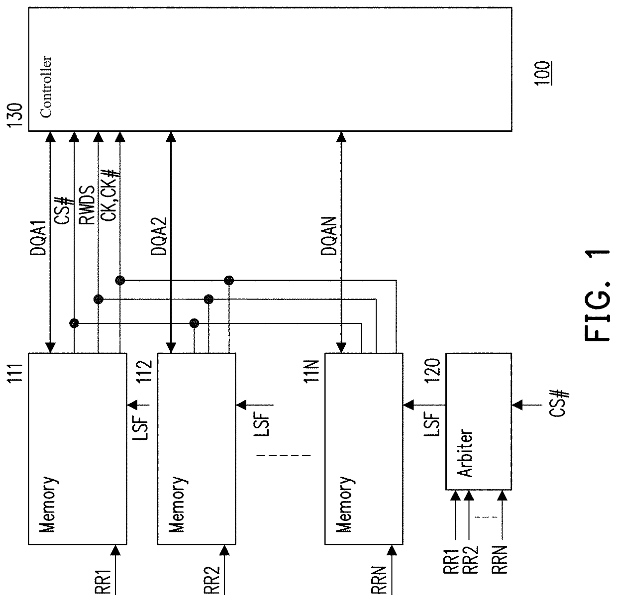
[0017]Please refer to FIG. 1. FIG. 1 is a schematic diagram of a pseudo static memory device according to an embodiment of the disclosure. A pseudo static memory device 100 includes memories 111-11N, an arbiter 120, and a controller 130. The memories 111-11N are dynamic random access memories. The memories 111-11N generate multiple self-refresh request signals RR1-RRN, and each of the self-refresh request signals RR1-RRN indicates a time period during which a corresponding each of the memories 111-11N performs a self-refresh operation. The self-refresh request signals RR1-RRN are provided to the arbiter 120. The arbiter 120 receives a chip enable signal CS#. The arbiter 120 further generates a latency synch...


PUM


Abstract

A pseudo static memory device includes multiple memories, an arbiter and a controller. The memories respectively generate multiple self-refresh request signals. Each of the self-refresh request signals indicates a time period for performing self-refresh operation of corresponding memory. The arbiter receives the self-refresh request signals and generates a latency synchronize flag during the memories being enabled. The controller decides an accessing latency for accessing the memories during an accessing operation according to the latency synchronize flag.

Description

CROSS-REFERENCE TO RELATED APPLICATION[0001]This application claims the priority benefit of Taiwan application serial no. 109124457, filed on Jul. 20, 2020. The entirety of the above-mentioned patent application is hereby incorporated by reference herein and made a part of this specification.BACKGROUND1. Technical Field[0002]The disclosure relates to a pseudo static memory device, and particularly relates to a pseudo static memory device that is capable of dynamically adjusting an accessing latency.2. Description of Related Art[0003]In electronic devices that require static memory, a pseudo static memory device using dynamic random access memory has been proposed because of the increasing capacity of the static memory required. The pseudo static memory device is popular especially in IoT devices.[0004]The dynamic random access memory needs to perform self-refresh operations, therefore, when the dynamic random access memory performs a self-refresh operation while the pseudo static me...

Claims


Application Information

Patent Timeline
Patent Type & Authority Patents(United States)
IPC IPC(8): G11C7/00G11C11/406
CPCG11C11/40615G11C2211/4066
Inventor HOU, CHIEN-TITU, YING-TE
Owner WINBOND ELECTRONICS CORP
Why Eureka
Try Eureka