Joint mobilization apparatus
a joint mobilization and apparatus technology, applied in the field of rehabilitation apparatus, can solve the problems of therapists' burden, high labor intensity and time consumption, and achieve the effect of facilitating patient use independently and reducing the burden of physical strength of therapists
- Summary
- Abstract
- Description
- Claims
- Application Information
AI Technical Summary
Benefits of technology
Problems solved by technology
Method used
Image
Examples
first embodiment
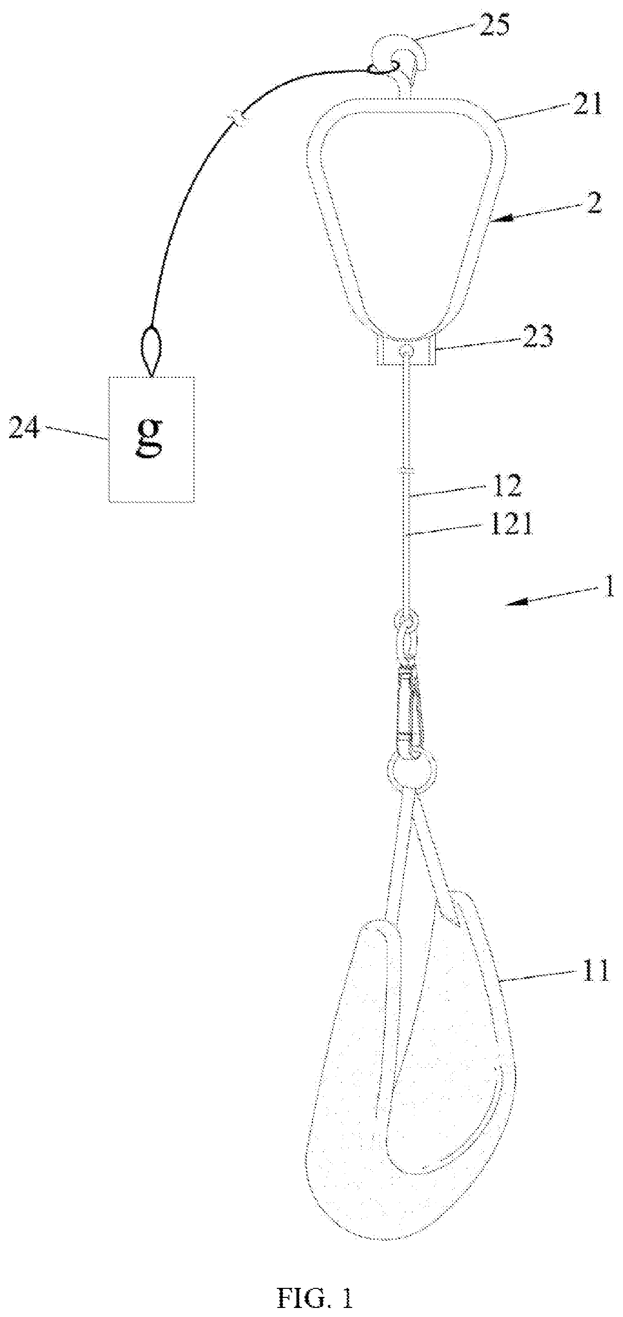
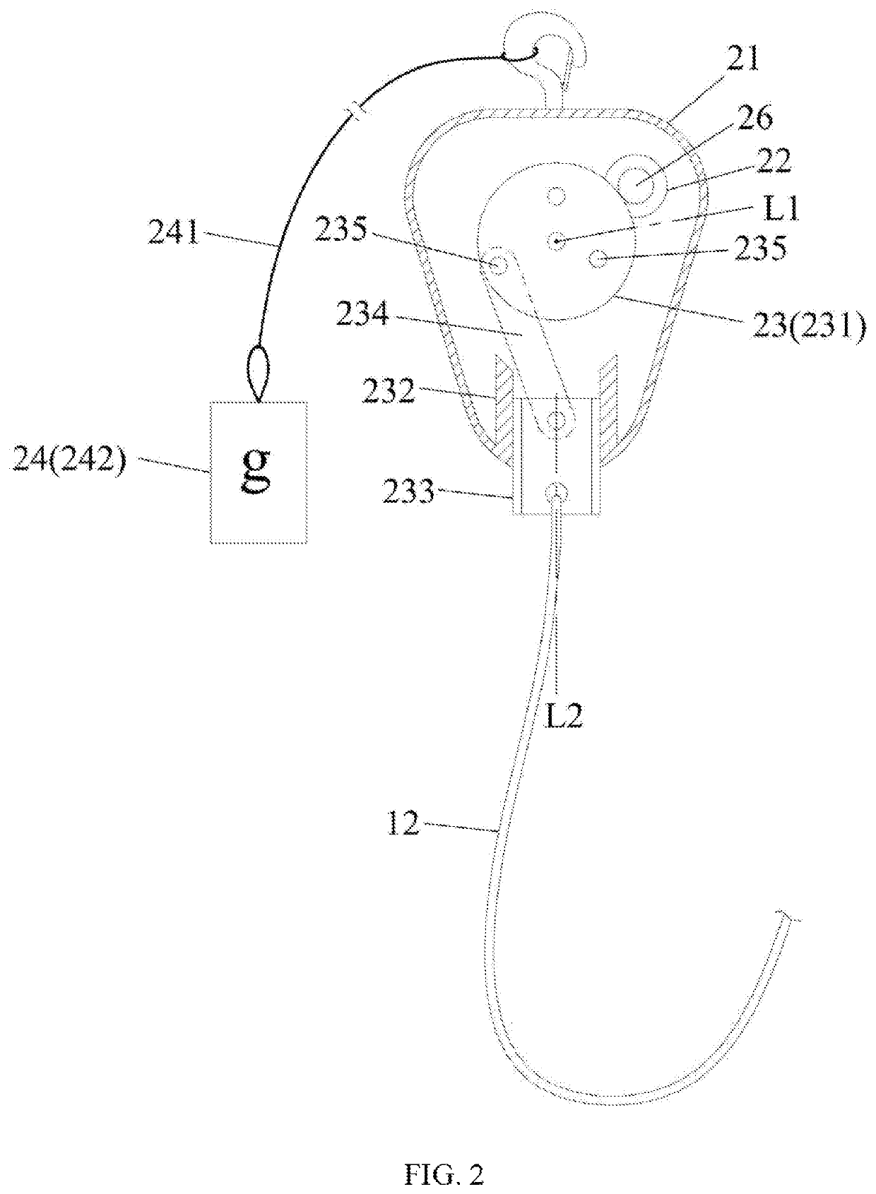
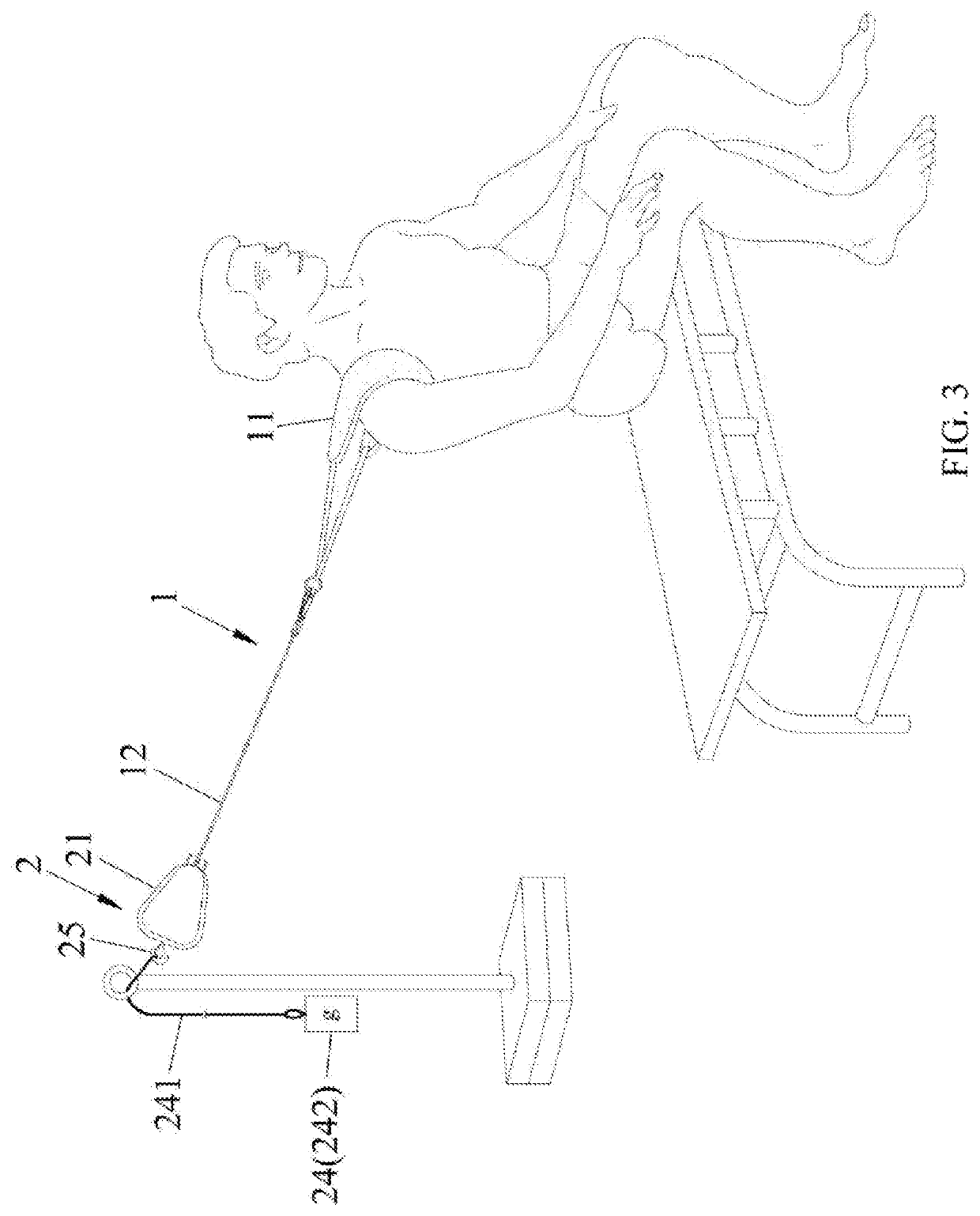
[0029]Please refer to FIGS. 1 and 2. a joint mobilization apparatus of the present invention comprises a pulling unit 1 and a power unit 2.
[0030]The pulling unit 1 comprises a wearable member set 11 and rope set 12. The wearable member set 11 is configured to mount on the patient's joint part, and the rope set 12 is connected to the wearable member set 11. In this embodiment, the rope set 12 has a rope 121 connected to the wearable member set 11 and the power unit 2.
[0031]The power unit 2 is configured to provide power of reciprocatingly pulling the rope set 12, the power unit 2 comprises a shell member 21, a motor 22 disposed on the shell member 21, a reciprocation mechanism 23 disposed on the shell member 21 and connected to the motor 22 and the rope set 12, a weight member set 24 detachably connected to the shell member 21, and a hook member 25 disposed on the shell member 21. The reciprocation mechanism 23 is driven by the motor 22 to reciprocate relative to the shell member 21,...
second embodiment
[0035]Please refer to FIGS. 6 and 10, which show a joint mobilization apparatus of the present invention applicable to mobilize the patient's shoulder joint, the joint mobilization apparatus comprises a base unit 3, a power unit 4, a pulling unit 5, a chair 6, and a turning unit 7.
[0036]Please refer to FIGS. 6 and 7. The base unit 3 comprises a base 31, a base frame 32 disposed on the base 31 and extended upwardly, two positioning member sets 33 respectively disposed on left and right sides of a top of the base frame 32, and two swingable arms 34 connected to the positioning member set 33 and respectively extended in directions away from the base frame. Each of the plurality of swingable arms 34 comprises a first end 341 connected to the positioning member set 33, and a second end 342 opposite to the first end 341. Relative to the positioning member set 33, the second end 342 is rotatable about the fourth axis IA which passes through the positioning member set 33 and is extended in ...
PUM
 Abstract
Description
Claims
Application Information
 - R&D
- Intellectual Property
- Life Sciences
- Materials
- Tech Scout
- Unparalleled Data Quality
- Higher Quality Content
- 60% Fewer Hallucinations
Browse by: Latest US Patents, China's latest patents, Technical Efficacy Thesaurus, Application Domain, Technology Topic, Popular Technical Reports.
© 2025 PatSnap. All rights reserved.Legal|Privacy policy|Modern Slavery Act Transparency Statement|Sitemap|About US| Contact US: help@patsnap.com


