Display device

a technology of display panel and display panel, which is applied in the field of display panel, can solve the problems of degrading the quality of the display panel, difficult to dispose of the display operation components in the active area, etc., and achieves the effects of reducing the load, reducing the load of data lines, and reducing the load

Active Publication Date: 2022-06-21
LG DISPLAY CO LTD
View PDF29 Cites 2 Cited by
  • Summary
  • Abstract
  • Description
  • Claims
  • Application Information

AI Technical Summary

Benefits of technology

[0010]Embodiments of the present invention provide an improved arrangement structure of signal lines including a sensor area provided in an active area of a display panel, the arrangement structure allowing subpixels disposed around the sensor area to be driven.
[0011]Embodiments provide a solution able to improve the uniformity of images displayed by the subpixels located in the active area, around the sensor area.
[0018]In addition, data lines disposed in the boundary area located around the hole area can be disposed on different layers according to subpixels driven through the data lines, thereby reducing an increase in load, which would otherwise be caused by an increase in the length of the data lines disposed in the boundary area.
[0019]Accordingly, degradations in luminance that would otherwise be caused by an increase in the load of data lines through which subpixels located around the hole area are driven can be prevented, thereby improving the uniformity of images displayed by subpixels around the hole area.

Problems solved by technology

In this case, since a sensor area in which a sensor is disposed is present in an active area in which display operation components, such as signal lines and subpixels, are disposed, it may be difficult to dispose the display operation components in the active area, which can be problematic.
Accordingly, the presence of a sensor in the active area can degrade the quality of the display panel.

Method used


Image

  • Display device
  • Display device
  • Display device

Examples


Embodiment Construction

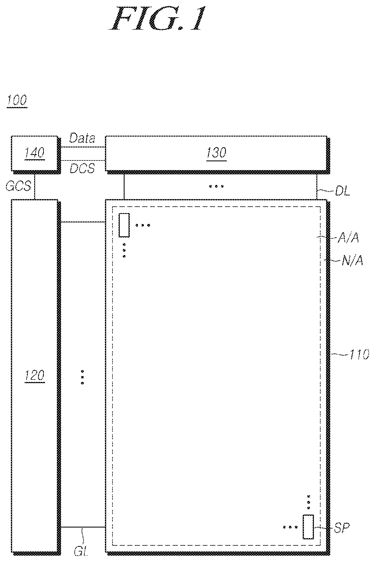
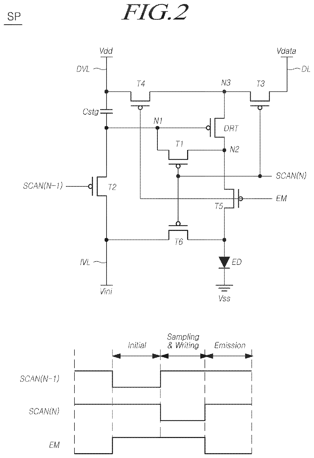
[0031]In the following description of examples or embodiments of the present invention, reference will be made to the accompanying drawings in which it is shown by way of illustration specific examples or embodiments that can be implemented, and in which the same reference numerals and signs can be used to designate the same or like components even when they are shown in different accompanying drawings from one another. Further, in the following description of examples or embodiments of the present invention, detailed descriptions of well-known functions and components incorporated herein will be omitted when it is determined that the description can make the subject matter in some embodiments of the present invention rather unclear. The terms such as “including”, “having”, “containing”, “constituting”“make up of”, and “formed of” used herein are generally intended to allow other components to be added unless the terms are used with the term “only.” As used herein, singular forms ar...


PUM

PropertyMeasurementUnit
areaaaaaaaaaaa
circumferenceaaaaaaaaaa
voltageaaaaaaaaaa

Abstract

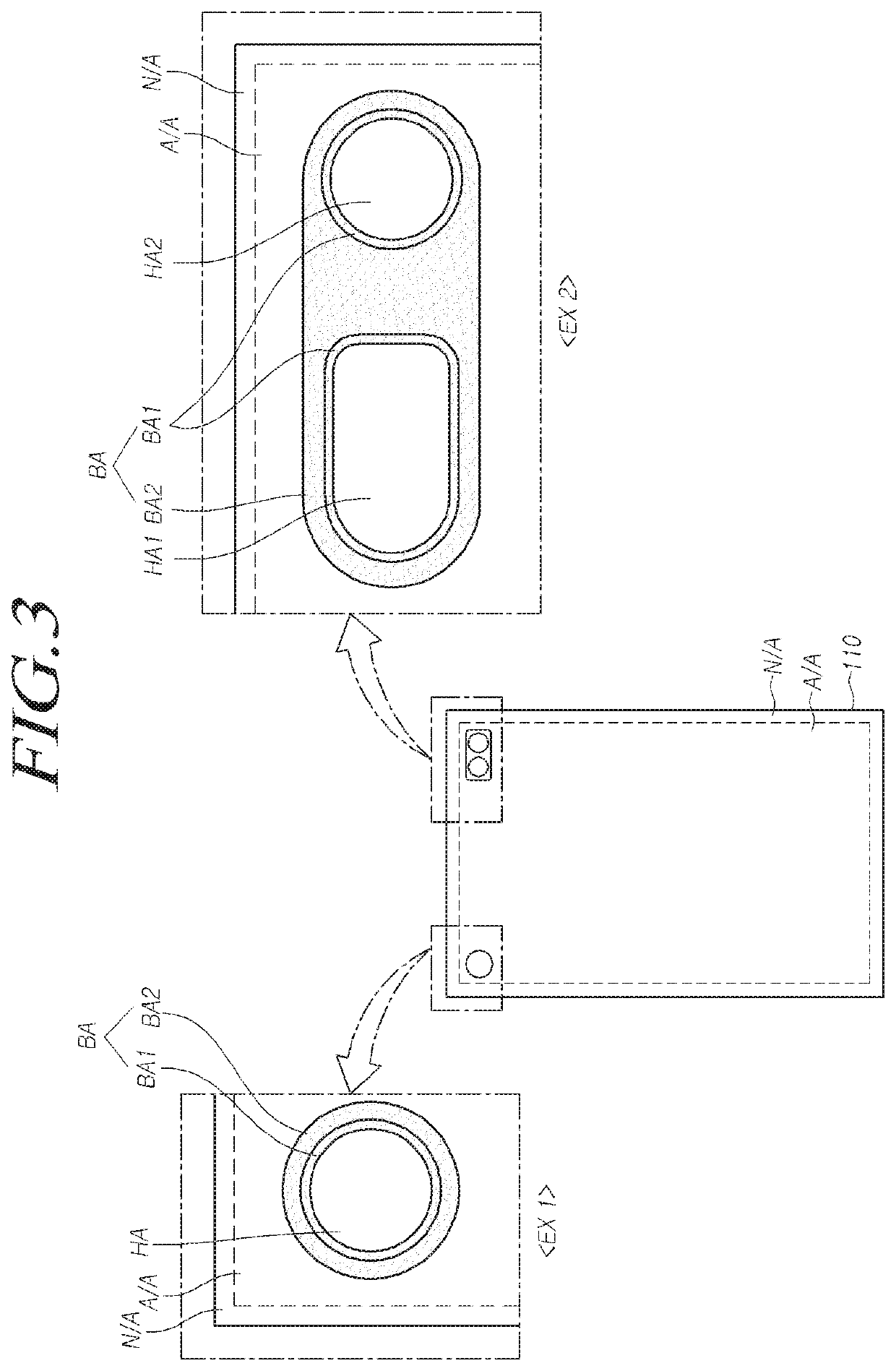
Provided is a display device having a structure in which a hole area in which camera sensors or the like are disposed is included in an active area of a display panel. Data lines among a plurality of data lines bypassing the hole area are disposed on different layers to prevent an increase in the load of data lines, through which green subpixels are driven. Degradations in the luminance of subpixels disposed around the hole area and driven through the data lines bypassing the hole area are prevented. The uniformity of luminance around the hole area is improved.

Description

CROSS REFERENCE TO RELATED APPLICATION[0001]This application claims priority to Korean Patent Application No. 10-2019-0117722, filed in the Republic of Korea on Sep. 24, 2019, the entire contents of which are hereby expressly incorporated by reference for all purposes as if fully set forth herein into the present application.BACKGROUNDField[0002]Embodiments relate to a display device.Description of Related Art[0003]Along with the development of the information society, demand for a variety of types of image display devices is increasing. In this regard, a range of display devices, such as liquid crystal display (LCD) devices and organic light-emitting diode (OLED) display devices, have come into widespread use.[0004]Such a display device can include a display panel having a plurality of subpixels to display images and a variety of drive circuits to drive the subpixels arranged on the display panel.[0005]In addition, the display device can provide a function of detecting an object ap...

Claims


Application Information

Patent Timeline
Patent Type & Authority Patents(United States)
IPC IPC(8): G09G3/32G09G3/20
CPCG09G3/32G09G3/2003G09G2310/0267G09G2310/0275G09G3/2074G09G3/3291G09G2320/0233G09G2300/0426G09G2300/0819G09G2300/0842G09G2300/0861G09G3/3233G09G2300/0452G09G2300/0443G09G2354/00G06F1/1637G06F1/1643G06F1/1686H10K59/131G09G3/3225H10K50/80G09G3/3208G09G2300/02G09G2300/04H10K59/00
Inventor LEE, JUNGGYULIM, JINHOJO, BOEUN
Owner LG DISPLAY CO LTD
Why Eureka
Try Eureka