Wire with terminal
a terminal and wire technology, applied in the direction of connection insulation, coupling device details, coupling device connections, etc., to achieve the effect of enhancing the water cut-off effect in the terminal
- Summary
- Abstract
- Description
- Claims
- Application Information
AI Technical Summary
Benefits of technology
Problems solved by technology
Method used
Image
Examples
first embodiment
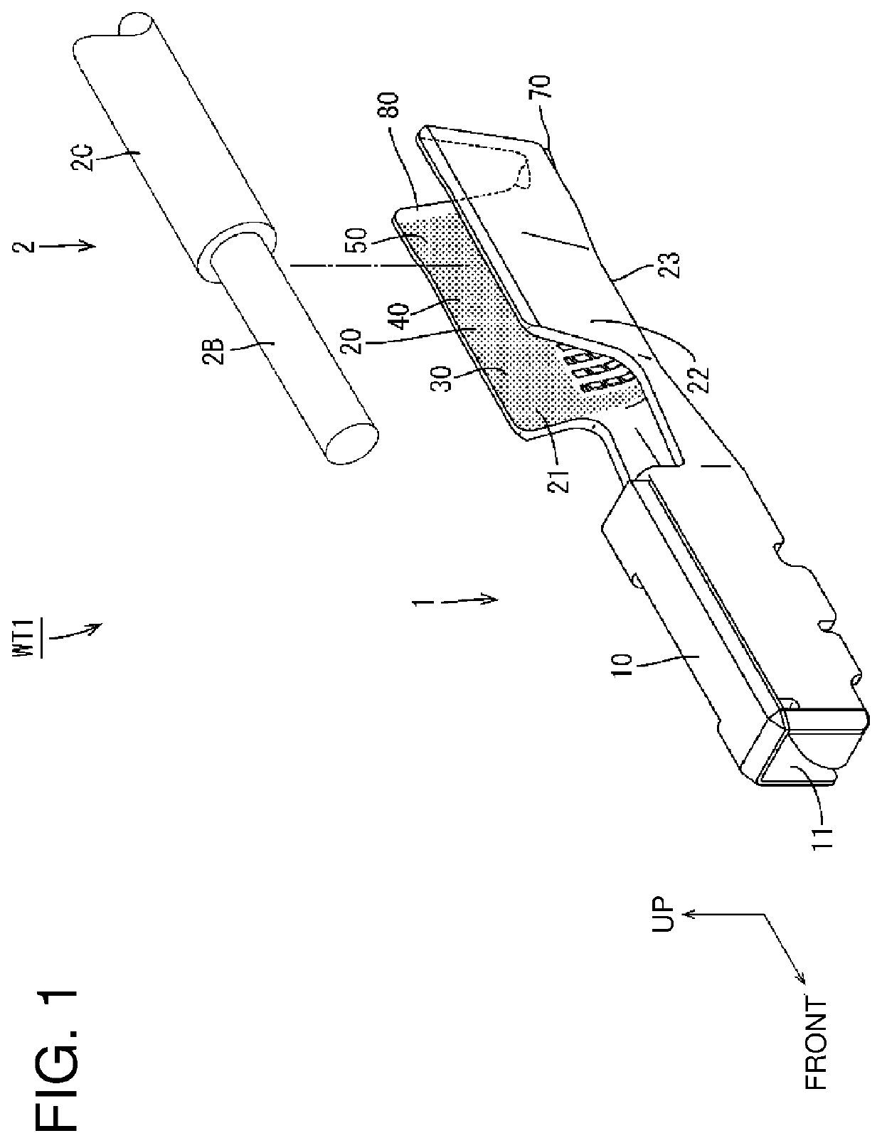
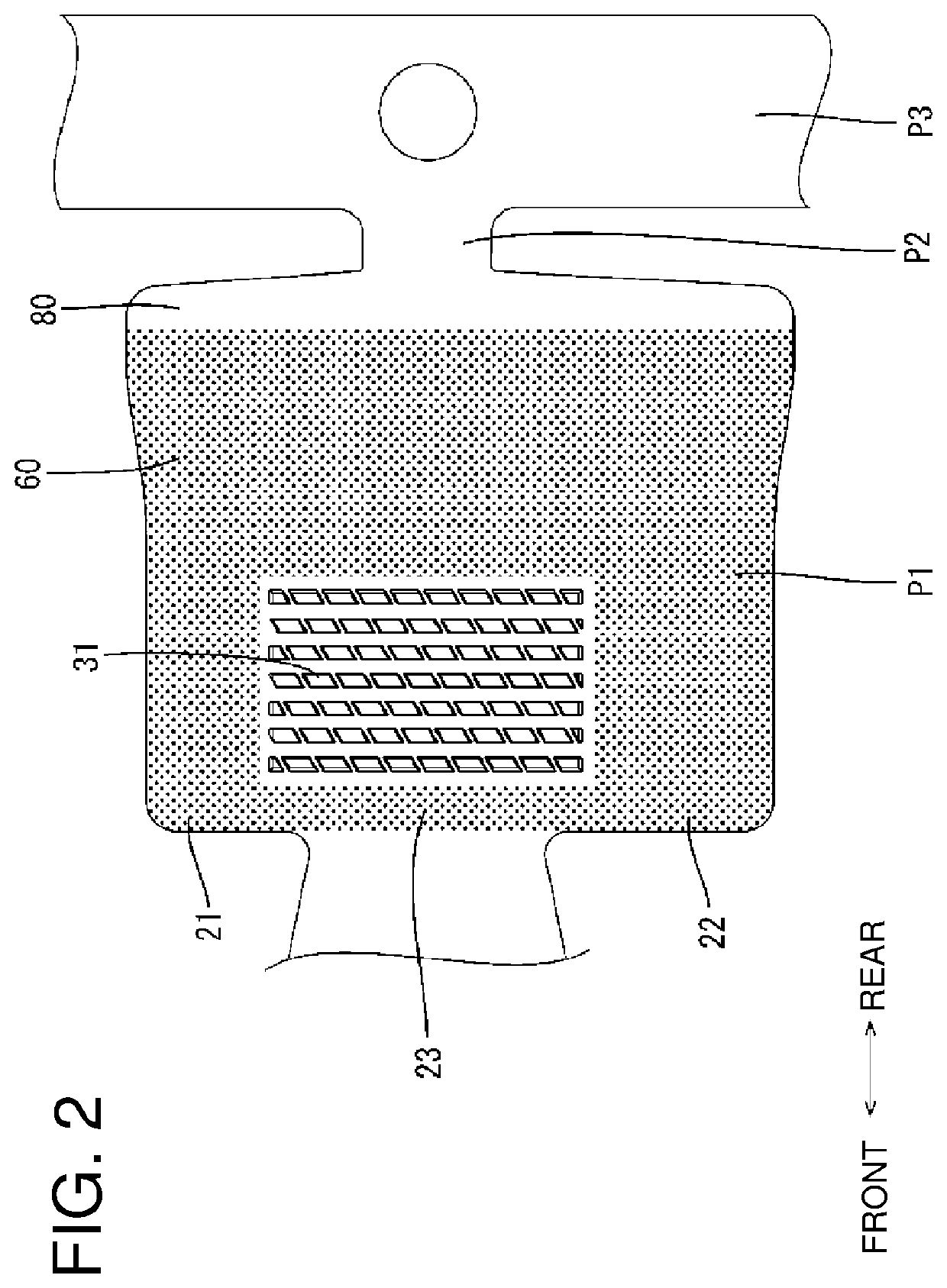
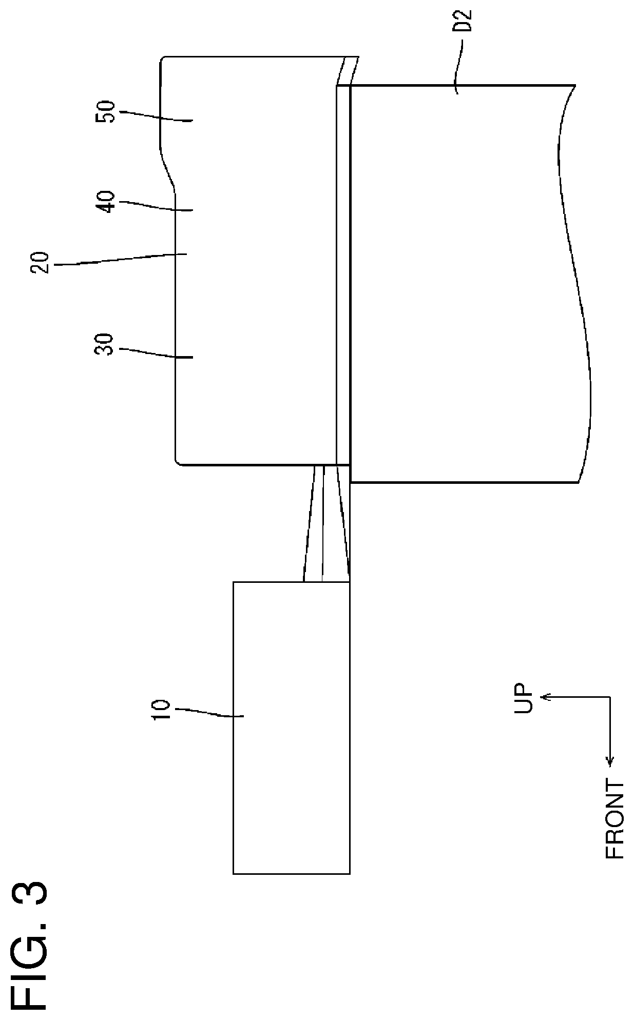
[0031]A first embodiment is described with reference to FIGS. 1 to 8.
[0032]This embodiment relates to a wire with terminal WT1 including a female terminal 1 to be connected to a mating terminal and a wire 2 connected to the terminal 1. The wire 2 is a coated wire including a core 2B and an insulation coating 2C covering around the core 2B, and the core 2B is exposed at an end of the wire 2. As shown in FIG. 1, the terminal 1 includes a terminal contact portion 10 having an opening 11 for receiving the mating terminal fitting, and a wire connecting portion 20 to be connected to the end of the wire 2. In the following description, a vertical direction is based on FIG. 1 and a side toward which the wire 2 is pulled out from the wire connecting portion 20 (right side in FIG. 3) is referred to as a rear side.
[0033]As shown in FIG. 1, the wire connecting portion 20 is open upward as a whole in a state before the wire 2 is connected. The wire connecting portion 20 includes a core crimping ...
second embodiment
[0053]Next, a second embodiment is described with reference to FIG. 9. A wire with terminal WT101 of this embodiment differs from the wire with terminal of the first embodiment in that a parallel extending portion 190 is further provided in addition to a rear extending portion 80 as a rear end part of a wire connecting portion 120 of a terminal 101. In this embodiment, components corresponding to those of the first embodiment are denoted by reference signs obtained by adding 100 to the reference signs of the first embodiment. The same configuration, functions and effects as those of the first embodiment are not described and the same components as those of the first embodiment are denoted by the same reference signs.
[0054]The parallel extending portion 190 has a tubular shape connected to the rear end of the rear extending portion 80 over an entire circumference. A wire 2 extending rearward from the rear extending portion 80 is surrounded by the parallel extending portion 190. A cei...
third embodiment
[0056]Next, a third embodiment is described with reference to FIG. 10. Only the bottom portion 23 of the rear extending portion 80 is constituted by the oblique extending portion 70 in the second embodiment. A wire with terminal WT201 of this embodiment differs from the wire with terminal of the second embodiment in that a bottom portion 23 and a ceiling portion 24 of a rear extending portion 80 are respectively constituted by an oblique extending portion 70 in a wire connecting portion 220 of a terminal 201. Components corresponding to those of the second embodiment are denoted by reference signs obtained by adding 100 to the reference signs of the second embodiment. The same configuration, functions and effects as those of the second embodiment are not described and the same components as those of the second embodiment are denoted by the same reference signs.
[0057]According to this configuration, since a thickness of a water cut-off member 60 between the ceiling portion 24 of the ...
PUM
| Property | Measurement | Unit |
|---|---|---|
| circumference | aaaaa | aaaaa |
| diameter | aaaaa | aaaaa |
| flat shape | aaaaa | aaaaa |
Abstract
Description
Claims
Application Information
 - R&D
- Intellectual Property
- Life Sciences
- Materials
- Tech Scout
- Unparalleled Data Quality
- Higher Quality Content
- 60% Fewer Hallucinations
Browse by: Latest US Patents, China's latest patents, Technical Efficacy Thesaurus, Application Domain, Technology Topic, Popular Technical Reports.
© 2025 PatSnap. All rights reserved.Legal|Privacy policy|Modern Slavery Act Transparency Statement|Sitemap|About US| Contact US: help@patsnap.com


