Film-forming device

a film-forming device and film-forming technology, which is applied in the direction of coatings, metallic material coating processes, chemical vapor deposition coatings, etc., can solve the problems of short time the material gas is retained in the processing container, the material gas is also short on the deposition target, and the percentage of material gas discharged without being deposited on the workpiece surfa

Active Publication Date: 2022-07-05
MURATA MFG CO LTD
View PDF31 Cites 12 Cited by
  • Summary
  • Abstract
  • Description
  • Claims
  • Application Information

AI Technical Summary

Benefits of technology

[0005]In the film-forming device according to Patent Literature 1, a Zr source gas dispersion nozzle to supply a material gas into a processing container is arranged opposite to an exhaust port. In such a structure, the material gas easily flows toward the exhaust port, and the time the material gas is retained in the processing container is short. Due to the short retention time, the time the material gas is retained on workpieces (deposition targets) is also short, and the percentage of the material gas discharged without being deposited on workpiece surfaces is high.
[0006]This results in a large amount of wasted material gas and longer deposition time.
[0008]The present invention was made to solve the above problems, and aims to provide a film-forming device capable of uniformly depositing deposition material on workpieces in a short deposition time.
[0014]The present invention provides a film-forming device capable of uniformly depositing on workpieces in a short deposition time.

Problems solved by technology

In such a structure, the material gas easily flows toward the exhaust port, and the time the material gas is retained in the processing container is short.
Due to the short retention time, the time the material gas is retained on workpieces (deposition targets) is also short, and the percentage of the material gas discharged without being deposited on workpiece surfaces is high.
This results in a large amount of wasted material gas and longer deposition time.
This also results in non-uniform deposition on the workpieces.

Method used


Image

  • Film-forming device
  • Film-forming device
  • Film-forming device

Examples


Embodiment Construction

[0020]The film-forming device of the present invention is described below.

[0021]The present invention is not limited to the following preferred embodiments, and may be suitably modified without departing from the gist of the present invention. Combinations of two or more preferred features described in the following preferred features are also within the scope of the present invention.

[0022]The term “horizontally” as used herein does not necessarily refer to a strict horizontal direction. For example, the term includes a direction inclined by about ±10° relative to the horizontal direction. Similarly, the terms “vertically” and “vertical direction” as used herein do not necessarily refer to a strict vertical direction. For example, the term includes a direction inclined by about ±10° relative to the vertical direction.

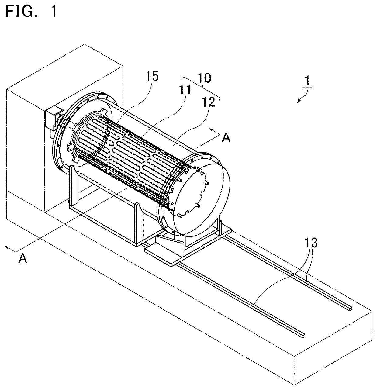
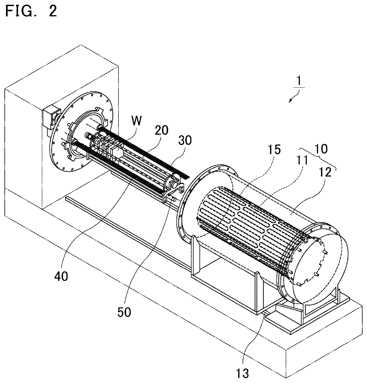
[0023]FIG. 1 is a schematic perspective view of a film-forming device according to an embodiment of the present invention. FIG. 2 is a schematic perspective view of a ...


PUM

PropertyMeasurementUnit
timeaaaaaaaaaa
deposition timeaaaaaaaaaa
cylindrical shapeaaaaaaaaaa

Abstract

A film-forming device that includes a cylindrical chamber capable of maintaining vacuum therein, a workpiece holder that is constructed to align and hold workpieces to be processed in multiple stages such that main surfaces of the workpieces are oriented in a vertical direction relative to a central axis of the chamber, a deposition material supply pipe, a modifier supply pipe, a carrier gas supply pipe, and an exhaust mechanism, wherein in a cross section of the chamber in a direction parallel to the main surfaces of the workpieces, the exhaust mechanism is located on a side opposite to an opening direction of gas outlets of the deposition, modifier, and carrier gas supply pipes, and a total gas flow from the deposition, modifier, and carrier gas supply pipes is symmetric about a centerline of the chamber.

Description

CROSS REFERENCE TO RELATED APPLICATIONS[0001]The present application is a continuation of International application No. PCT / JP2018 / 044925, filed Dec. 6, 2018, which claims priority to Japanese Patent Application No. 2017-246513, filed Dec. 22, 2017, the entire contents of each of which are incorporated herein by reference.FIELD OF THE INVENTION[0002]The present invention relates to a film-forming device.BACKGROUND OF THE INVENTION[0003]Film-forming devices based on atomic layer deposition (ALD) are known as devices that form oxide films on substrates to be processed, such as semiconductor wafers.[0004]Patent Literature 1 (JP 5221089 B) discloses a deposition method and a film-forming device based on atomic layer deposition.SUMMARY OF THE INVENTION[0005]In the film-forming device according to Patent Literature 1, a Zr source gas dispersion nozzle to supply a material gas into a processing container is arranged opposite to an exhaust port. In such a structure, the material gas easily ...

Claims


Application Information

Patent Timeline
Patent Type & Authority Patents(United States)
IPC IPC(8): C23C16/44C23C16/455C23C16/458H01L21/673
CPCC23C16/4412C23C16/4587C23C16/45502C23C16/45534C23C16/45544C23C16/45546C23C16/45548C23C16/45578C23C16/45587H01L21/67313H01L21/31H01L21/67109H01L21/67754
Inventor CHIKAISHI, YASUHIROYAMANE, SHIGEKI
Owner MURATA MFG CO LTD
Why Eureka
Try Eureka