
Work vehicle

a technology for working vehicles and sub-units, applied in the direction of vehicles, superstructures, transportation and packaging, etc., can solve the problem that the cabin may have a risk of water entering through the hole, too

Active Publication Date: 2022-07-12
KUBOTA CORP
View PDF11 Cites 0 Cited by
  • Summary
  • Abstract
  • Description
  • Claims
  • Application Information

AI Technical Summary

Benefits of technology

[0006]With the structure described above, since the receiver is above the roof, the receiver can easily receive the positional information from the satellite. Also, since the receiver is supported at the cabin framework of the cabin via the stay, the supporting structure of the receiver is able to be simply configured without need for a roof (a dedicated roof) to which the receiver is attachable, and further the receiver is able to be securely supported by the cabin framework which has relatively high rigidity in the cabin. Still further, since work to form a hole in the roof is not required, there is no risk that water enters the cabin through the hole.
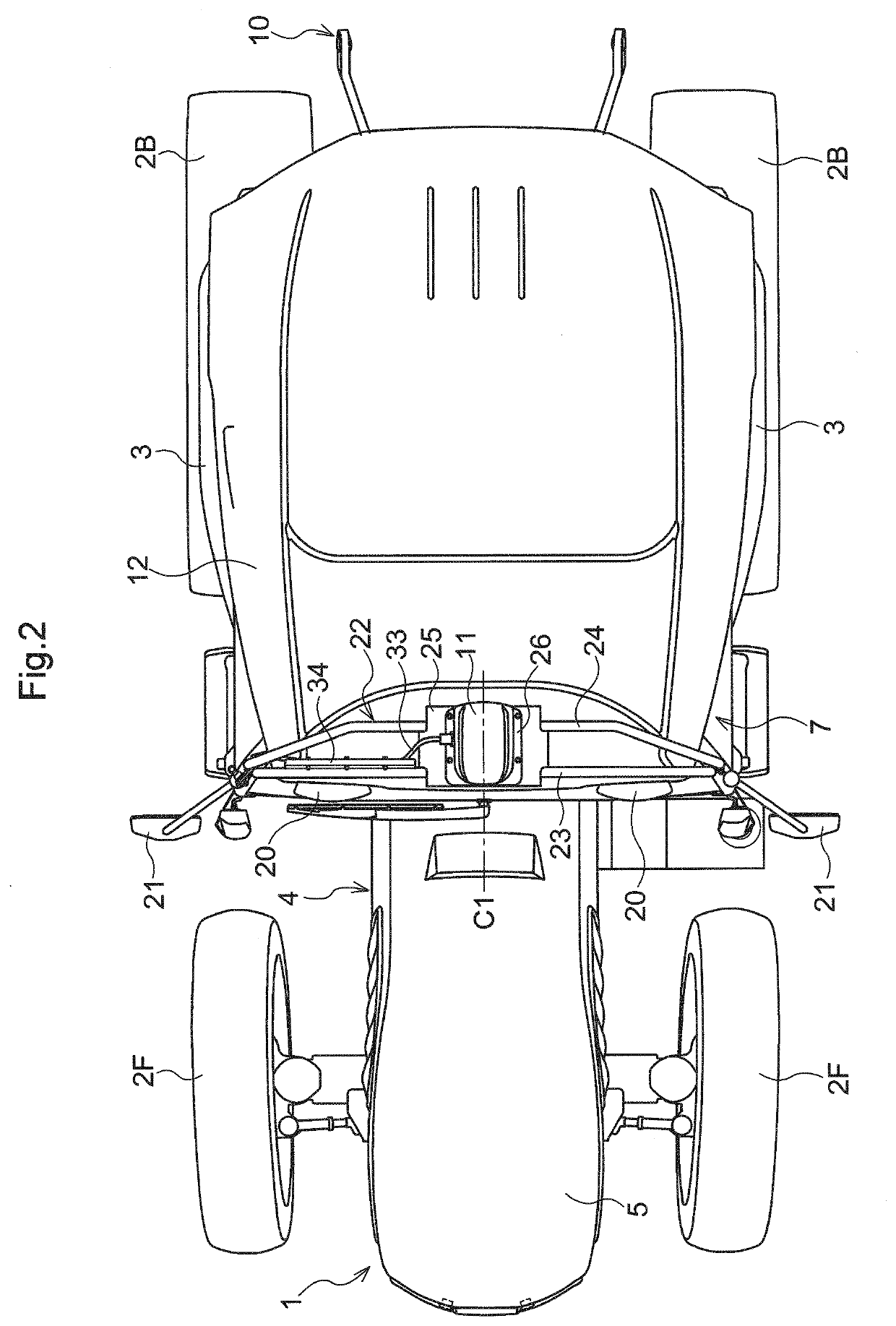
[0008]With the structure described above, the receiver receives the positional information on an approximately front / rear central portion of a traveling vehicle body. As a result, when the traveling vehicle body travels automatically along a target travel route, for example, less correction of the positional information received by the receiver is required.
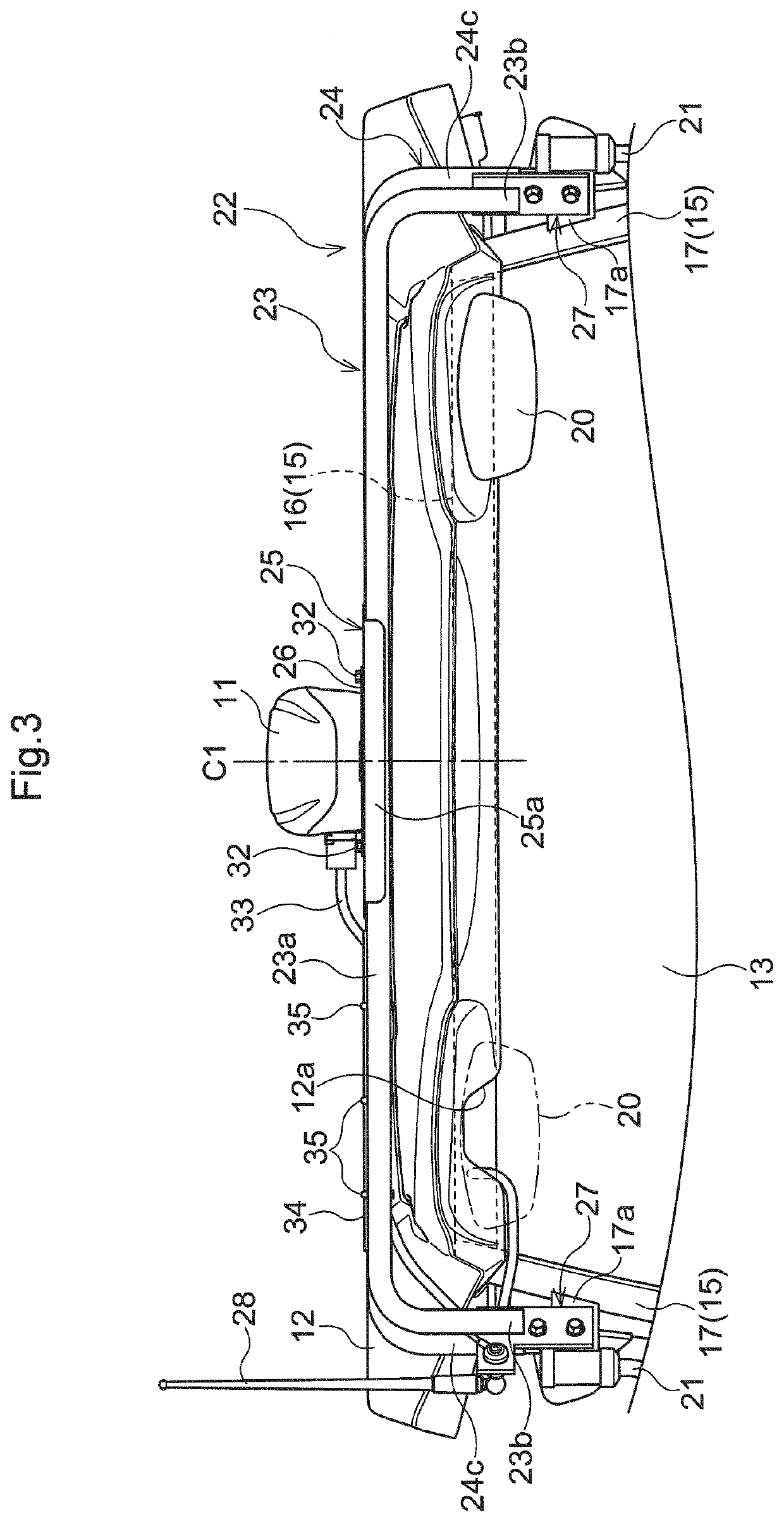
[0010]With the structure described above, the supporting structure of the receiver is able to be configured without interference of the elongated member with the roof. Also, both the right and left end portions of the elongated member is able to be securely supported by the front pillars.
[0012]With the structure described above, the elongated member and the side mirror share the support. As a result, the number of parts related to the supporting structure of the receiver is able to be reduced.
[0014]With the structure described above, the receiver is supported at a plurality of the elongated members via the pedestal. As a result, the supporting structure of the receiver is able to have a rigid configuration.

Problems solved by technology

In such as case, since a work to form a hole in the roof is required, the cabin may have a risk of entrance of water through the hole, too.

Method used


Image

  • Work vehicle
  • Work vehicle
  • Work vehicle

Examples


Embodiment Construction

[0025]Preferred embodiments of the present invention will be described with reference to the drawings.

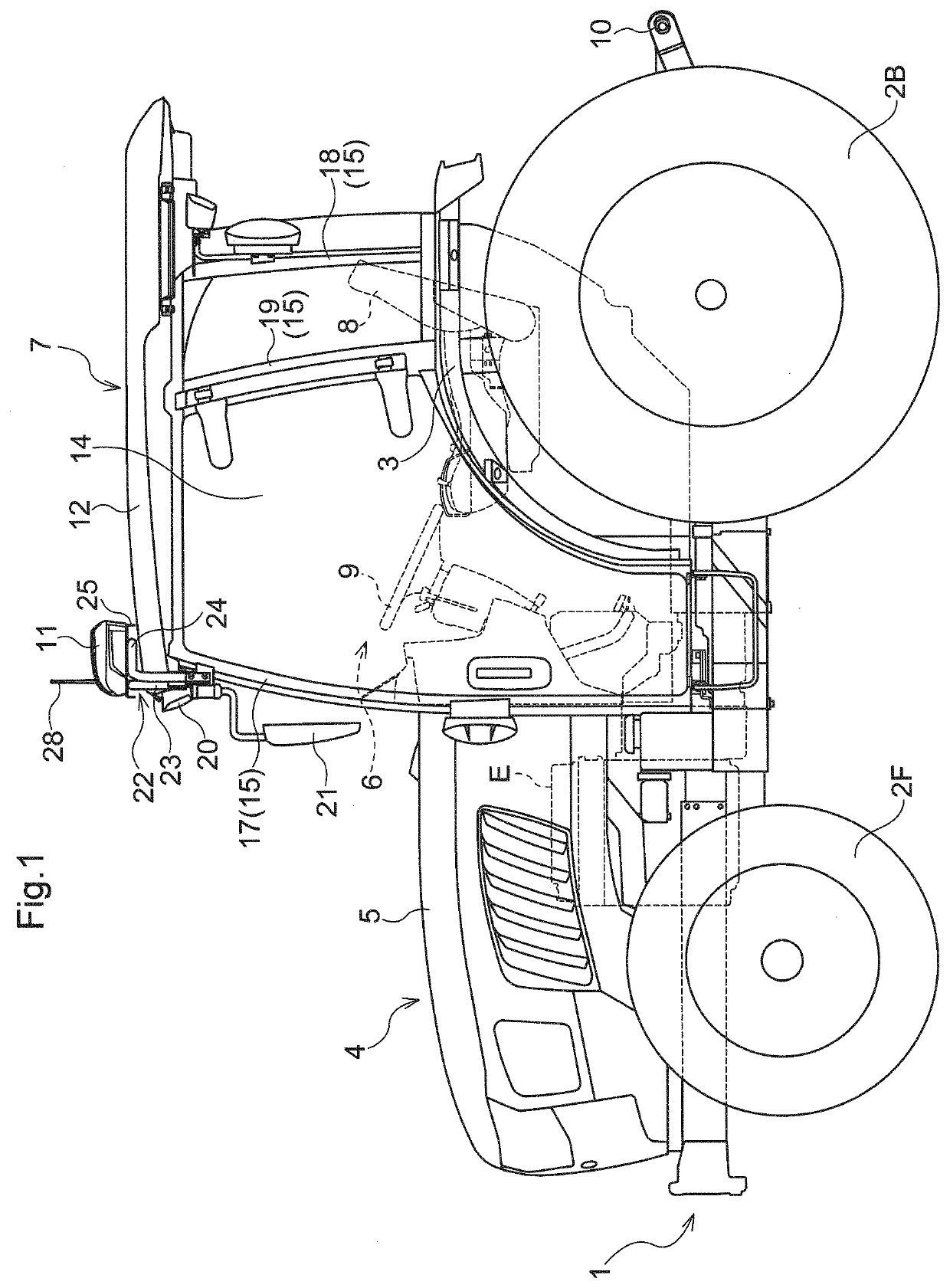
[0026]FIG. 1 and FIG. 2 show a tractor (work vehicle). The tractor is provided with a traveling vehicle body 1. The traveling vehicle body 1 is a four-wheel-drive traveling vehicle body, for example. The traveling vehicle body 1 is provided with a pair of drivable and steerable right and left front wheels 2F, and a pair of drivable right and left rear wheels 2B. A pair of right and left fenders 3 are disposed to cover the pair of right and left rear wheels 2B, respectively.

[0027]At a front half portion of traveling vehicle body 1, there is provided an engine section 4. The engine section 4 is provided with an engine E, and a hood 5 which houses the engine E. At a rear half portion of the traveling vehicle body 1, there are provided a driver section 6 in which a driver boards, and a cabin 7 which covers the driver section 6. At the driver section 6, there are provided a driver's seat...


PUM


Abstract

A work vehicle includes a cabin covering a driver section, a receiver to receive positional information from a satellite, and a stay to support the receiver. The receiver is above a roof of the cabin and supported at a cabin framework of the cabin via the stay.

Description

BACKGROUND OF THE INVENTION1. Field of the Invention[0001]The present invention relates to a work vehicle including a reception device to receive positional information from a satellite.2. Description of the Related Art[0002]As a work vehicle as described above, a work vehicle disclosed in Japanese Unexamined Patent Application Publication No. 2018-114924 is conventionally known, for example. The work vehicle disclosed in Japanese Unexamined Patent Application Publication No. 2018-114924 includes a cabin (cabin (4) in Japanese Unexamined Patent Application Publication No. 2018-114924) which covers a driver section, and a reception device (antenna unit (61) in Japanese Unexamined Patent Application Publication No. 2018-114924) which receives positional information from a satellite. In the work vehicle disclosed in Japanese Unexamined Patent Application Publication No. 2018-114924, the reception device is attached to an upper face portion of a roof of the cabin to secure preferable re...

Claims


Application Information

Patent Timeline
Patent Type & Authority Patents(United States)
IPC IPC(8): B60R11/02B62D33/06B60R1/00B62D25/04B60R11/00
CPCB60R11/0258B60R1/006B60R11/02B62D25/04B62D33/0617B60R2011/004B60R1/06B62D33/06B60Y2200/221B60Y2400/82
Inventor MISAKI, SHINJI
Owner KUBOTA CORP
Learn More