
Wire connection bracket assembly

Active Publication Date: 2022-07-12
DOUGLAS JOEL +1
View PDF15 Cites 0 Cited by
  • Summary
  • Abstract
  • Description
  • Claims
  • Application Information

AI Technical Summary

Benefits of technology

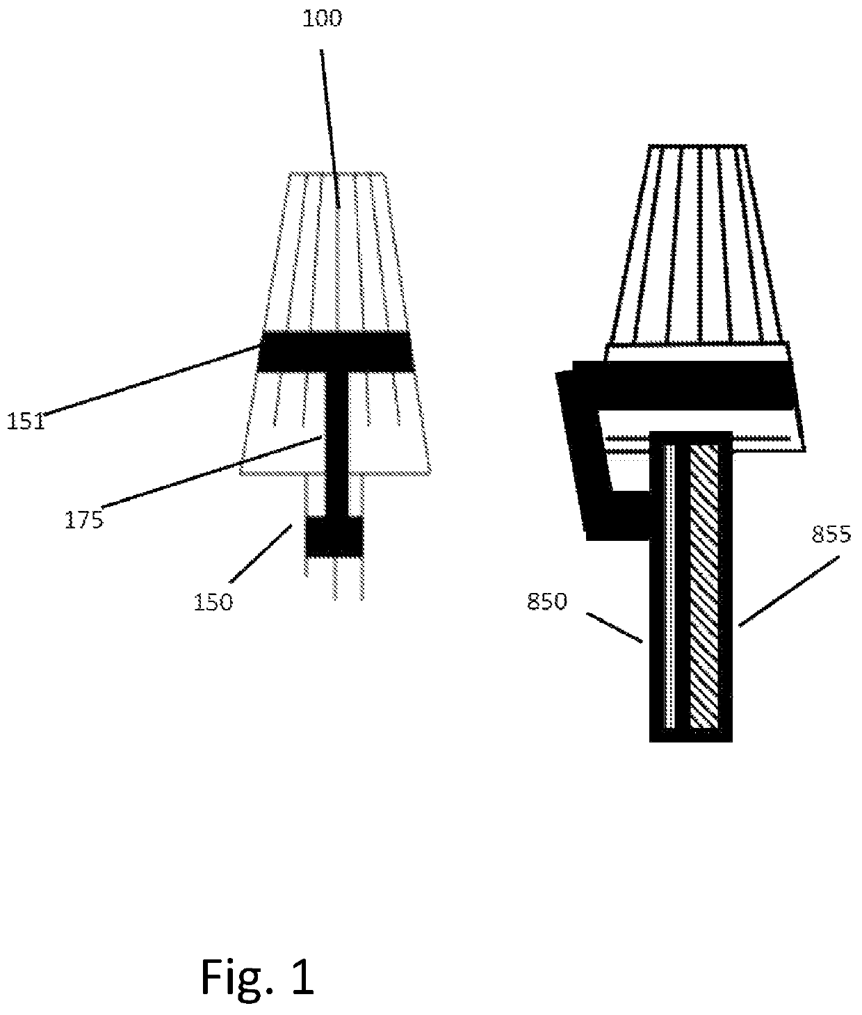
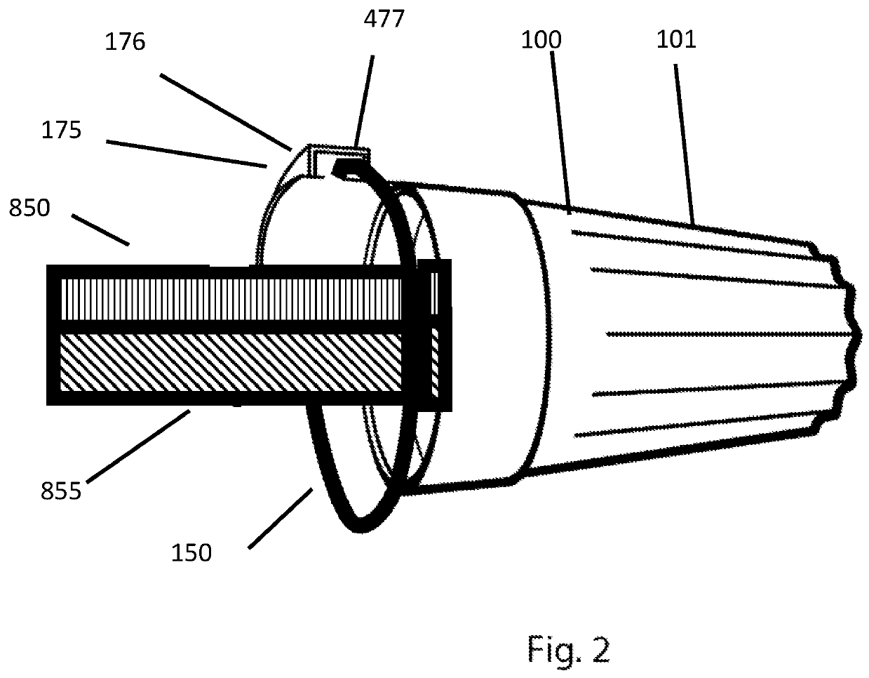
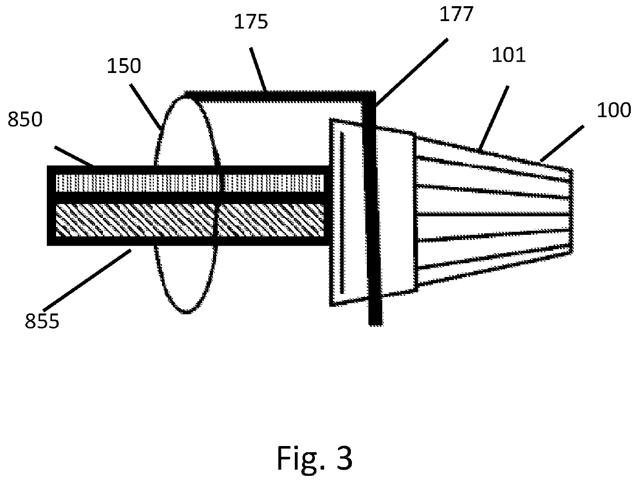
The present invention is a clamping mechanism that prevents wiring or cabling from coming loose or being pulled apart, improving the safety and reliability of the connector. It can be used in conjunction with existing connectors to improve the reliability of a connection. Additionally, the invention provides strain relief for fiber-optic connections, preventing damage to the wires. The parts necessary for installation are assembled into a simple to use package, making the installation process easy for the user.

Problems solved by technology

The main issue seen in the prior art is that the wires can sometimes become loose from improper installation, vibration, or movement and fall out of the enclosure.
If a user does not rotate a wire nut or connector for instance with adequate amount of turns then the wires may not be joined tightly enough.
This can cause the wires to become loose or fall out of the wire nut or connector when subjected to stress.
This exposes the wires to other electrical connections which increase safety and fire hazard concerns.
Another issue with the prior art and current available electrical connectors for joining wires is the use of crimp designs, if the crimp is not applied with enough pressure, the wires may also fall out.
This also exposes wires which pose a safety and liability concern for installers.
Additionally, tools designed to install wire nuts burden users with an additional and unnecessary cost, and also if used improperly can cause the wires to fall out of the insulating enclosure and thereby increase safety concerns.

Method used


Image

  • Wire connection bracket assembly
  • Wire connection bracket assembly
  • Wire connection bracket assembly

Examples


Embodiment Construction

[0039]While various aspects and features of certain embodiments have been summarized above, the following detailed description illustrates a few exemplary embodiments in further detail to enable one skilled in the art to practice such embodiments. The described examples are provided for illustrative purposes and are not intended to limit the scope of the invention.

[0040]In the following description, for the purposes of explanation, numerous specific details are set forth in order to provide a thorough understanding of the described embodiments. It will be apparent to one skilled in the art however that other embodiments of the present invention may be practiced without some of these specific details. Several embodiments are described herein, and while various features are ascribed to different embodiments, it should be appreciated that the features described with respect to one embodiment may be incorporated with other embodiments as well. By the same token however, no single featur...


PUM


Abstract

The invention relates to a method of connecting electrical wires, conductors, or connections together by rotating the connector ends in an enclosure to tightly twist the wire ends together and also includes a clamping mechanism to prevent the wires from untwisting, becoming loose, or falling out of the enclosure. The present invention increases the holding ability of current rotating tools for electrical wires and connections.

Description

[0001]This application claims the benefit of U.S. Provisional Patent Application No. 63 / 234,520 filed on Aug. 18, 2021, U.S. Provisional Patent Application No. 63 / 254,289 filed on Oct. 10, 2021, which are incorporated by reference herein in their entirety.COPYRIGHT STATEMENT[0002]A portion of the disclosure of this patent document contains material that is subject to copyright protection. The copyright owner has no objection to the facsimile reproduction by anyone of the patent document or the patent disclosure as it appears in the Patent and Trademark Office patent file or records, but otherwise reserves all copyright rights whatsoever.[0003]Trademarks used in the disclosure of the invention, and the applicants, make no claim to any trademarks referenced.BACKGROUND OF THE INVENTION1) Field of the Invention[0004]The invention relates to an apparatus for reinforcing wire and cable connections.2) Description of Related Art[0005]In construction, manufacturing facilities, and several ot...

Claims


Application Information

Patent Timeline
IPC IPC(8): H01R4/22H01R4/12H01R4/00H01R43/033H01R43/00
CPCH01R4/22H01R4/00H01R4/12
Inventor DOUGLAS, JOELLACHHMAN, SHEM
Owner DOUGLAS JOEL
Learn More