Supercharge Your Innovation With Domain-Expert AI Agents!

Staged telescopic screw assembly having different visual indicators

a technology of telescopic screw and visual indicator, which is applied in the direction of belt/chain/gearing, other medical devices, etc., can solve the problems of difficult to tell whether the assembly has properly reached its maximum extension, user may not know whether a full dose of the drug has been administered, and patient's hand strength is not sufficient, so as to improve visual distinction, prevent retraction, and readily visualize the progress of extension

Active Publication Date: 2022-07-19
WEST PHARM SERVICES IL LTD
View PDF1116 Cites 0 Cited by
  • Summary
  • Abstract
  • Description
  • Claims
  • Application Information

AI Technical Summary

Benefits of technology

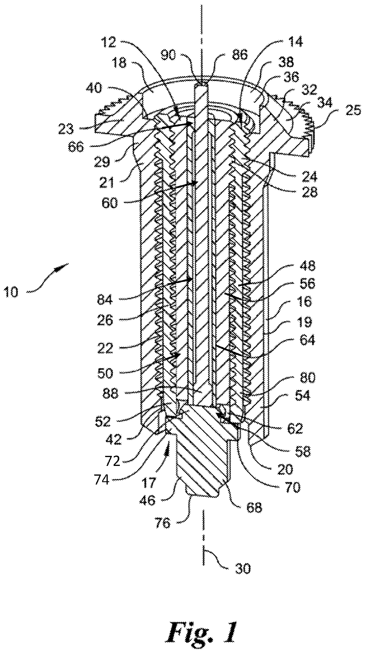
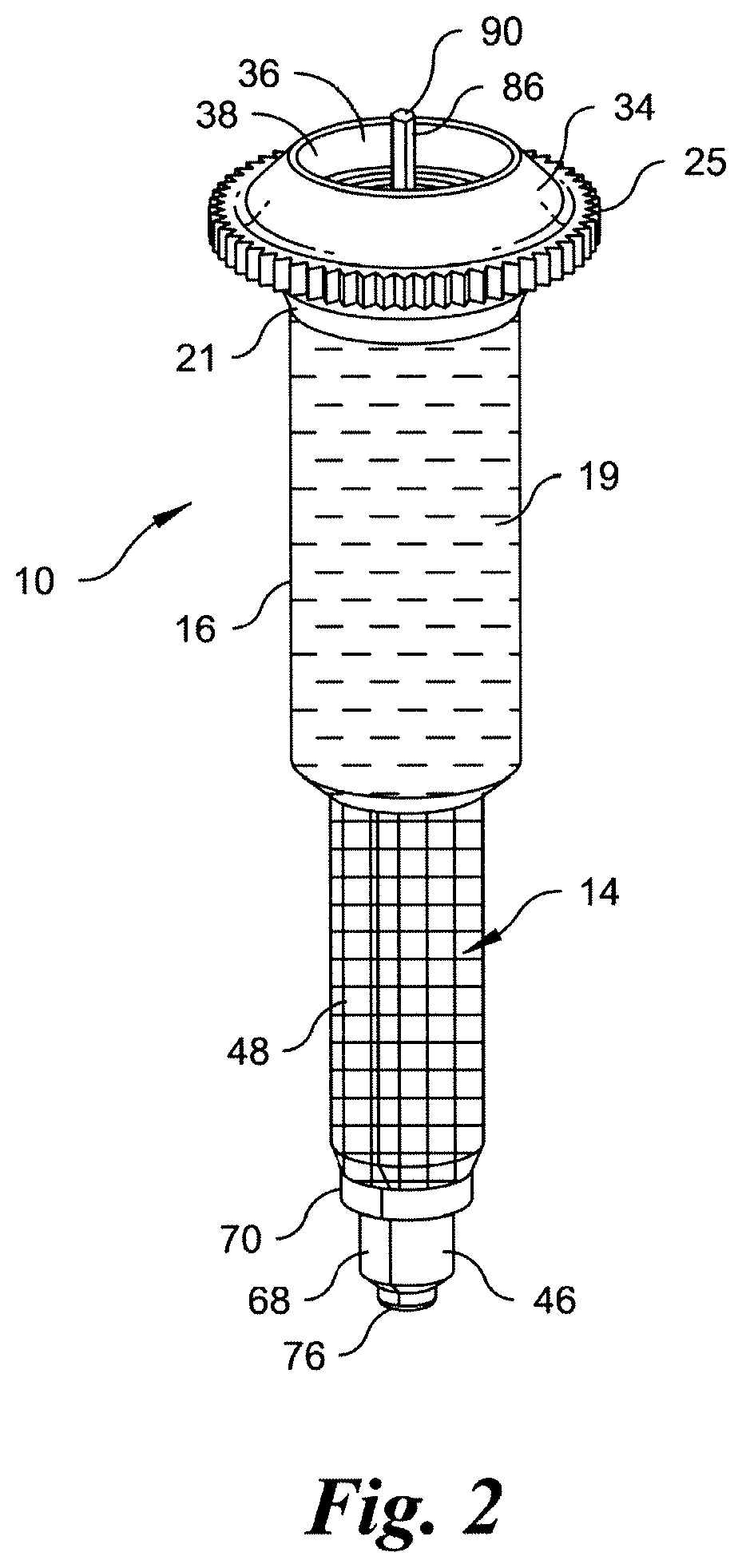
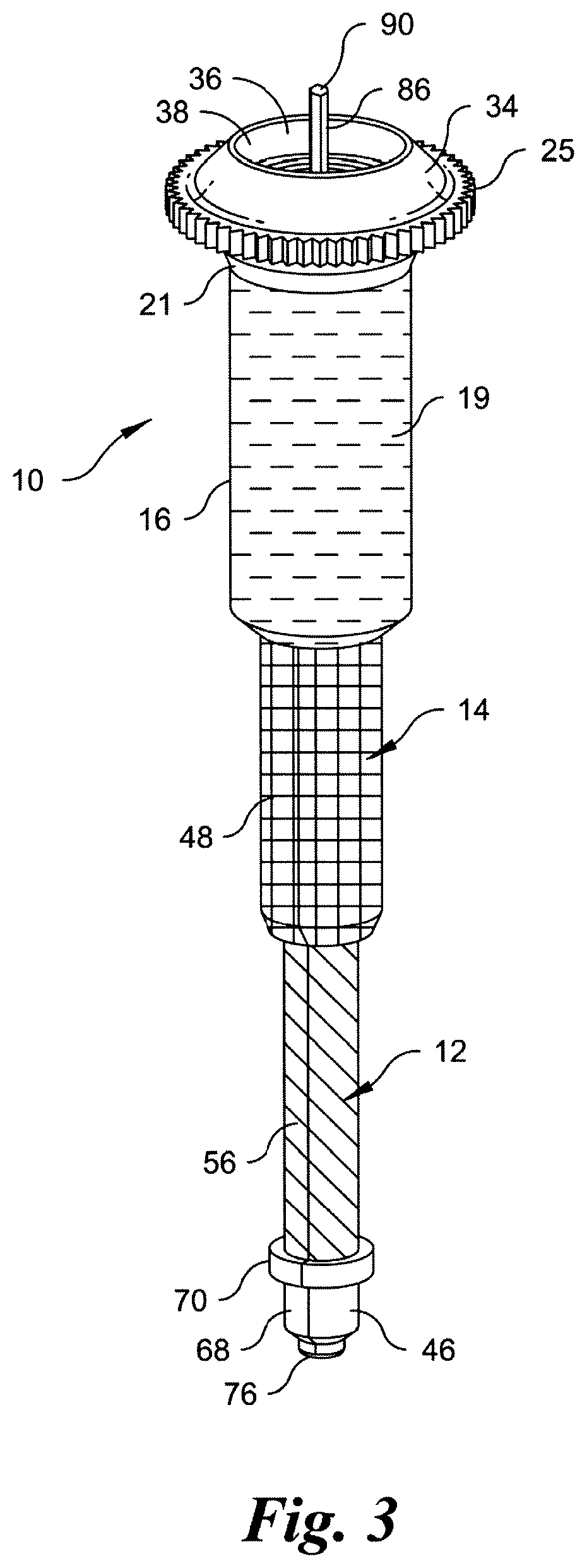
The present invention provides a telescopic screw assembly for an injector that allows for easy and convenient adjustment of the screw assembly's length. The screw assembly includes an inner screw, an outer screw, and a middle screw in a nested configuration. The assembly can be expanded or contracted by rotating the outer screw in one direction or the other. The inner and middle screws are visually distinguishable, and a rod member is engaged with the inner screw to prevent retraction and overextension of the screw assembly. The technical effects of this invention include improved ease of use and convenience in adjusting the length of the screw assembly, as well as improved visual identification and prevention of overextension.

Problems solved by technology

One drawback of a manually activated plunger is that patients must be relatively dexterous and have the required hand strength to push the plunger themselves.
One drawback of a telescopic assembly is that it can be difficult to tell whether the assembly has properly achieved its maximum extension.
Thus, a user may not know whether a full dose of the drug has been administered.
Another drawback of the telescopic assembly is that the assembly may extend all at once, or certain of the nested members may extend in a random sequential order.

Method used


Image

  • Staged telescopic screw assembly having different visual indicators
  • Staged telescopic screw assembly having different visual indicators
  • Staged telescopic screw assembly having different visual indicators

Examples


Embodiment Construction

[0013]Certain terminology is used in the following description for convenience only and is not limiting. The words “right,”“left,”“lower,” and “upper” designate directions in the drawings to which reference is made. The words “inwardly” or “distally” and “outwardly” or “proximally” refer to directions toward and away from, respectively, the geometric center or orientation of the telescopic screw assembly and related parts thereof. Unless specifically set forth herein, the terms “a”, “an” and “the” are not limited to one element but instead should be read as meaning “at least one”. The terminology includes the above-listed words, derivatives thereof and words of similar import.

[0014]It should also be understood that the terms “about,”“approximately,”“substantially” and like terms, used herein when referring to a dimension or characteristic of a component of the invention, indicate that the described dimension / characteristic is not a strict boundary or parameter and does not exclude m...


PUM


Abstract

A telescopic screw assembly for an injector includes an inner screw, an outer screw and a middle screw. The middle and outer screws are in a first threaded engagement, and the inner and middle screws are in a second threaded engagement. The inner screw is nested with the middle screw and the middle screw is nested with the outer screw in a contracted configuration of the screw assembly. Rotation of the outer screw in one direction advances the middle screw relative to the outer screw via the first threaded engagement and advances the inner screw relative to the middle screw via the second threaded engagement to telescopically extend the screw assembly into an expanded configuration. At least two of the inner, middle and outer screws are identified with a different visual indicator to enhance visual distinction between the screws, and readily visually indicate an extension progress of the screw assembly.

Description

CROSS-REFERENCE TO RELATED APPLICATIONS[0001]This application is a section 371 of International Application No. PCT / US17 / 22639, filed Mar. 16, 2017, which was published Sep. 21, 2017 under International Publication No. WO 2017 / 161076 A1, which claims the benefit of U.S. Provisional Application No. 62 / 309,111, titled “Staged Telescopic Screw Assembly With Color Coding”, filed on Mar. 16, 2016, the entire contents of which is incorporated by reference herein.BACKGROUND OF THE INVENTION[0002]The present invention relates generally to a telescopic screw assembly and more particularly to an injector having a staged telescopic screw assembly with a visual indicator showing the degree of extension of the telescopic screw assembly.[0003]Injectors or syringes are used to deliver specified quantities of drugs or medicine to a patient and typically include a chamber for storing the drug, a needle connected to the chamber through which the drug is delivered, and a plunger which pushes the medic...

Claims


Application Information

Patent Timeline
Patent Type & Authority Patents(United States)
IPC IPC(8): A61M5/315F16H25/20
CPCA61M5/31586A61M5/31511A61M5/31581F16H25/2056A61M2005/31508A61M2005/31518A61M2205/584
Inventor FARRIS, JASON W.SANTOS, JORGEMEYER, MARLAESPOSITO, ANTHONY G.
Owner WEST PHARM SERVICES IL LTD
Features
  • R&D
  • Intellectual Property
  • Life Sciences
  • Materials
  • Tech Scout
  • Unparalleled Data Quality
  • Higher Quality Content
  • 60% Fewer Hallucinations
Learn More