Systems, devices, and methods for physical surface tracking with a stylus device in an AR/VR environment

a technology of physical surface tracking and stylus device, which is applied in the direction of electric digital data processing, instruments, computing, etc., can solve the problems of inability to accurately measure the physical surface inability to control the movement of the stylus device, etc., to achieve the effect of only allowing coarse and inarticulate movement, ungainly control, and bulky grip controllers

Active Publication Date: 2022-07-26
LOGITECH EURO SA
View PDF9 Cites 7 Cited by
  • Summary
  • Abstract
  • Description
  • Claims
  • Application Information

AI Technical Summary

Benefits of technology

[0004]In some embodiments, a stylus tracking system can include one or more processors and a set of one or more sensors controlled by the one or more processors and configured to generate sensor data, the set of one or more sensors including at least from the group of: optical sensors and inertial sensors, the sensor data including location data usable to derive a location of a stylus device. The inertial sensors may include an inertial measurement unit (IMU). The one or more processors can be configured to: determine that a tip of the stylus device is in contact with a physical surface based on the sensor data; while the tip of the stylus device is determined to be in contact with the physical surface: determine a new location of the tip of the stylus device based on the location data; mitigate a tracking error of the determined new location of the tip of the stylus device based on: a translation of the new location of the tip of the stylus device from a three-dimensional (3D) space domain to a two-dimensional (2D) space domain that corresponds to the physical surface; and an adjustment of the new location of the tip of the stylus device in the 2D space based on a comparison of the new location and historical locations. The stylus device may be operable to facilitate a drawing of a virtual line that corresponds to the determined and mitigated new location of a tip of the stylus device, the virtual line comprised of virtual segments formed between the adjusted new location and other new locations.
[0005]In certain embodiments, the one or more processors can be further configured to apply a smoothing interpolation algorithm (e.g., Catmull-Rom splines) that improves an accuracy or continuity of the virtual segments. In some cases, the new location and the historical locations are defined by sample points, and the adjustment of the new location of the tip of the stylus device in the 2D space can be based on an application of a mean or median function to a latest n sample points including the new location and the historical locations. Then latest sample points can be between 2-10, and in some exemplary embodiments n is a latest 4 sample points, although other numbers of sample points can be used as further described below.
[0007]In some embodiments, a computer-implemented method of operating a stylus device system may include receiving sensor data from one or more sensors including at least from the group of: optical sensors and inertial sensors, the sensor data corresponding to a location of the stylus device, determining that a tip of the stylus device is in contact with a physical surface based on the sensor data, and while the tip is determined to be in contact with the physical surface: determining a new location of the tip of the stylus device based on the location data; mitigating a tracking error of the determined new location of the tip of the stylus device by: translating the new location of the tip of the stylus device from a three-dimensional (3D) space domain to a two-dimensional (2D) space domain that corresponds to the physical surface; and adjusting the new location of the tip of the stylus device in the 2D space based on a comparison of the new location and historical locations. The stylus device may be operable to facilitate the drawing of a virtual line that corresponds to the determined and mitigated new location of a tip of the stylus device, the virtual line comprised of virtual segments formed between each new tracked location of the tip of the stylus device.
[0008]In certain embodiments, the method can further include applying a smoothing interpolation algorithm (e.g., Catmull-Rom splines implementation) that improves an accuracy or continuity of the virtual segments between each new tracked location of the tip of the stylus device. In some aspects, the new location and the historical locations are defined by sample points, and wherein the adjusting of the new location of the tip of the stylus device in the 2D space includes: applying a mean or median function to a latest n sample points including the new location and the historical locations, wherein determining the new tracked location of the tip of the stylus device is based on a result of the applied mean or median function to the latest n sample points. The n latest sample points can be between 2-10, and in some exemplary embodiments n is a latest 4 sample points, although other numbers of sample points can be used as further described below.
[0010]In some embodiments, a non-transitory computer-program product tangibly embodied in a machine-readable non-transitory storage medium may include instructions configured to cause one or more processors to performing operations including: receiving sensor data from one or more sensors including at least from the group of: optical sensors and inertial sensors, the sensor data corresponding to a location of the stylus device; deriving a location of the stylus device based on the sensor data; determining that a tip of the stylus device is in contact with a physical surface based on the sensor data; and while the tip is determined to be in contact with the physical surface: determining a new location of the tip of the stylus device based on the location data; and mitigating a tracking error of the determined new location of the tip of the stylus device by: translating the new location of the tip of the stylus device from a three-dimensional (3D) space domain to a two-dimensional (2D) space domain that corresponds to the physical surface; and adjusting the new location of the tip of the stylus device in the 2D space based on a comparison of the new location and historical locations. The stylus device may be operable to facilitate the drawing of a virtual line that corresponds to the tracked location of a tip of the stylus device, the virtual line comprised of virtual segments formed between each new tracked location of the tip of the stylus device.
[0011]In certain embodiments, the instructions are further configured to cause one or more processors to performing operations including: applying a smoothing interpolation algorithm (e.g., Catmull-Rom splines implementation) that improves an accuracy or continuity of the virtual segments between each new tracked location of the tip of the stylus device. In some aspects, the new location and the historical locations can be defined by sample points. The adjusting of the new location of the tip of the stylus device in the 2D space may include applying a mean or median function to a latest n sample points including the new location and the historical locations, where determining the new tracked location of the tip of the stylus device is based on a result of the applied mean or median function to the latest n sample points. Then latest sample points can be between 2-10, and in some exemplary embodiments n is a latest 4 sample points, although other numbers of sample points can be used as further described below. In some implementations, the instructions are further configured to cause one or more processors to performing operations including: determining a current, real-time location of the tip of the stylus device based on the sensor data and generating a temporary segment that extends from the latest new tracked location of the tip of the stylus device to the current, real-time location of the tip of the stylus device, where the temporary segment can be updated as new locations of the tip of the stylus device are received.

Problems solved by technology

Despite their usefulness, pistol grip controllers in contemporary AR / VR systems tend to be bulky, unwieldy, cumbersome, and can induce fatigue in a user due to its weight and large tracking features that often include an obtrusive and protruding donut-shaped structure.
The pistol grip shape can help minimize fatigue as a user can typically hold objects in a pistol grip configuration for longer periods of time, but at the cost of only allowing coarse and inarticulate movement and ungainly control.
Despite their usefulness, many stylus-based systems are fraught with significant tracking deficiencies.
While a user may be able to finely articulate the stylus device as they would a pen, tracking those articulations with a high degree of accuracy is problematic, particularly with writing and other applications that require fine motor control.

Method used


Image

  • Systems, devices, and methods for physical surface tracking with a stylus device in an AR/VR environment
  • Systems, devices, and methods for physical surface tracking with a stylus device in an AR/VR environment
  • Systems, devices, and methods for physical surface tracking with a stylus device in an AR/VR environment

Examples


Embodiment Construction

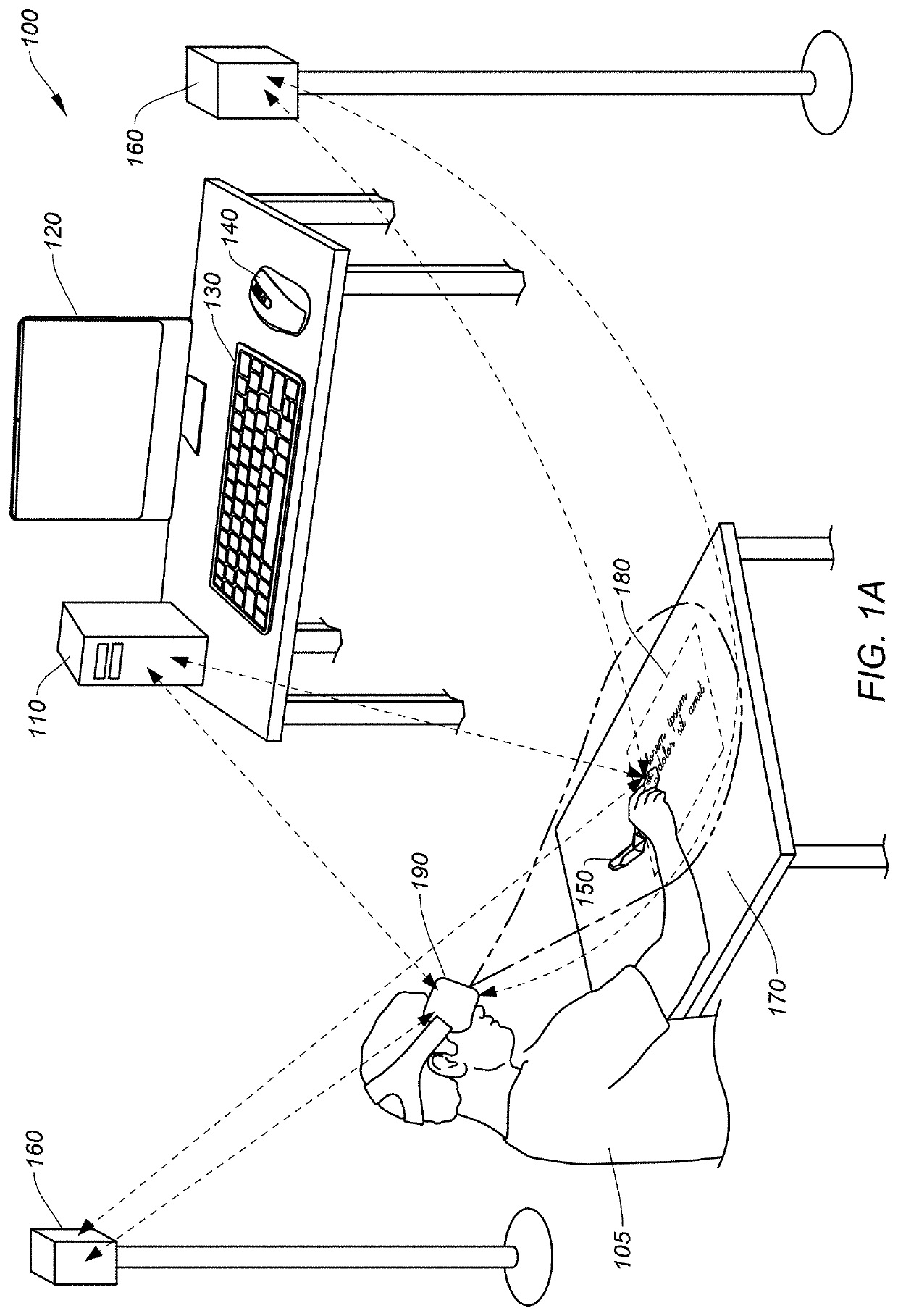
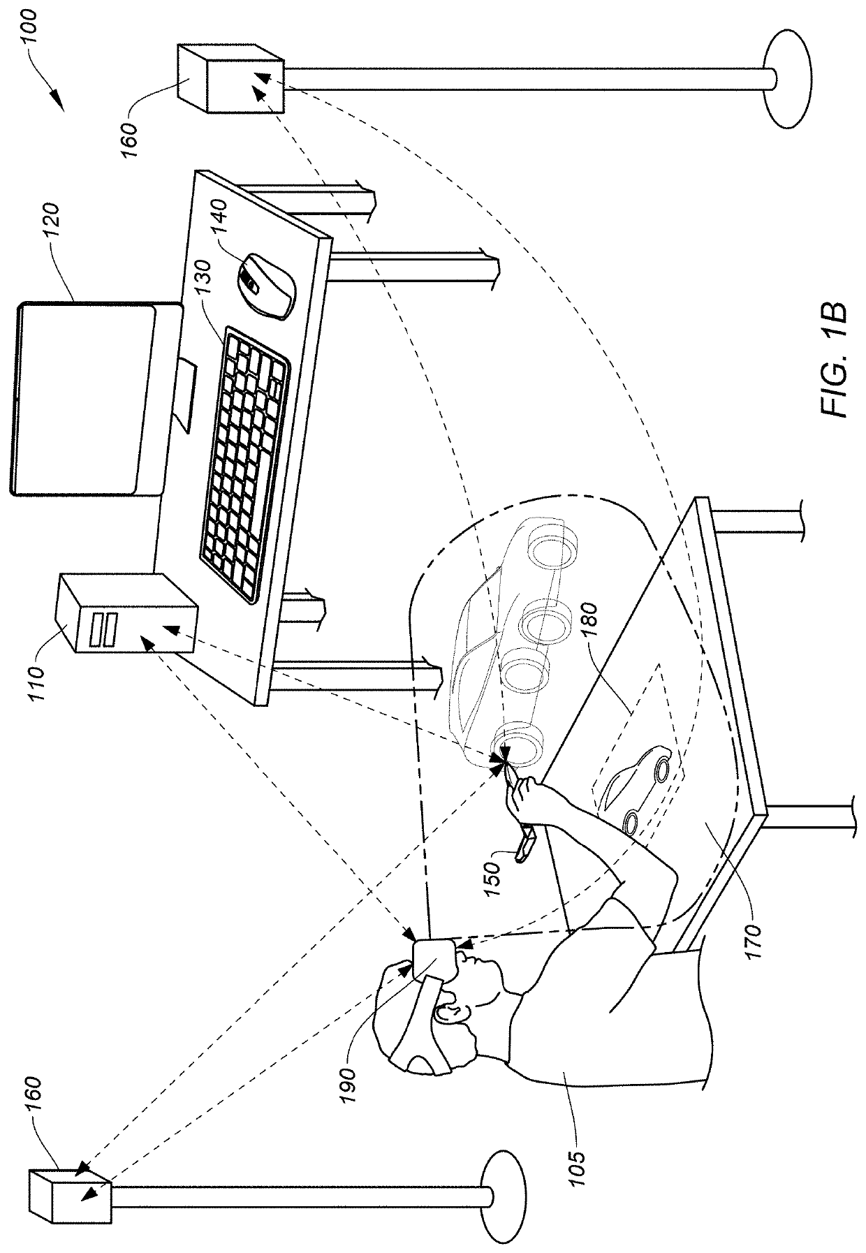
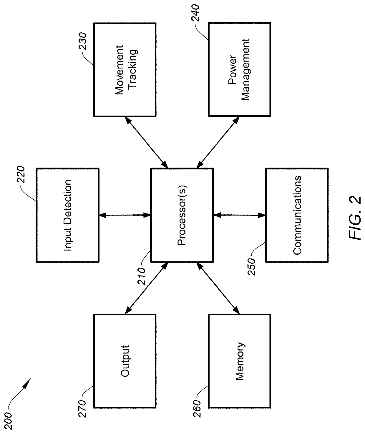
[0025]Embodiments of this invention are generally directed to control devices configured to operate in AR / VR-based systems. More specifically, some embodiments relate to a stylus device system configured to mitigate a tracking error of the stylus device while operating on a physical surface.

[0026]In the following description, for the purpose of explanation, numerous examples and details are set forth in order to provide an understanding of embodiments of the present invention. It will be evident, however, to one skilled in the art that certain embodiments can be practiced without some of these details, or with modifications or equivalents thereof.

[0027]To provide a high level, broad understanding of some aspects of the present disclosure, a non-limiting summary of certain embodiments are presented here. Stylus devices, as described herein, can be used as an input tool that can be used with a touchscreen-enabled device, such as tablet PCs, digital art tools, smart phones, or other de...


PUM


Abstract

A method includes receiving sensor data from one or more sensors that corresponds to a location of a stylus device and determining that a tip of the stylus device is in contact with a physical surface based on the sensor data. While in contact, the method includes determining a new location of the tip of the stylus device based on the location data, mitigating a tracking error of the determined new location of the tip of the stylus device by translating the new location from a 3D space domain to a 2D space domain that corresponds to the physical surface and adjusting the new location based on a comparison of the new location and historical locations.

Description

BACKGROUND[0001]Virtual, mixed, or augmented reality can be associated with a variety of applications that comprise immersive, highly visual, computer-simulated environments. These environments, commonly referred to as augmented-reality (AR), virtual-reality (VR), and mixed-reality (MR) environments, can simulate a physical presence of a user in a real or imagined world. The computer simulation of these environments can include computer rendered images, which can be presented by means of a graphical display. The display can be arranged as a head mounted display (HMD) that may encompass all or part of a user's field of view.[0002]A user can interface with the computer-simulated environment by means of a user interface device or peripheral device. A common controller type in many contemporary AR / VR systems is the pistol grip controller, which can typically operate with three or six degrees-of-freedom (DOF) of tracked movement, depending on the particular system. When immersed in a com...

Claims


Application Information

Patent Timeline
Patent Type & Authority Patents(United States)
IPC IPC(8): G06F3/0354G06F3/0346G06F3/03G06F3/038
CPCG06F3/03545G06F3/038G06F3/0325G06F3/0346G06F3/011
Inventor GUTIERREZ, MARIOWALDRON, PHILIPZELLWEGER, FABIENO'SULLIVAN, DAMIEN
Owner LOGITECH EURO SA
Why Eureka
Try Eureka