Battery module having bus bar and battery pack

a battery module and bus bar technology, applied in the field of battery modules, can solve the problems of degrading heat dissipation performance, degrading energy efficiency, and degrading weldability, and achieve the effects of improving resistance welding efficiency and bonding reliability, and being easy to position

Active Publication Date: 2022-07-26
LG ENERGY SOLUTION LTD
View PDF29 Cites 4 Cited by
  • Summary
  • Abstract
  • Description
  • Claims
  • Application Information

AI Technical Summary

Benefits of technology

[0024]According to an aspect of the present disclosure, according to the battery module of the present disclosure, by forming the first connection extension portion and the second connection extension portion of the bus bar, which protrude and extend in different horizontal directions from the internal boundary of the coupling opening and connecting and fixing the electrode terminal to the end portions of the first connection extension portion and the second connection extension portion by resistance welding, an amount of electricity flowing between the first connection extension portion and the second connection extension portion may be increased effectively, and thus, efficiency of resistance welding and bonding reliability may be improved.
[0025]Also, according to an aspect of another embodiment of the present disclosure, by setting a width of portions of the first connection extension portion and the second connection extension portion connected to a boundary of a coupling opening is narrowed to be smaller than the other portions of a body of the first connection extension portion and the second connection extension portion, electrical resistance of the narrowed width portion may be increased, and thus, an amount of electricity flowing through the electrode terminal and the end portions of the first connection extension portion and the second connection extension portion may be further increased, thereby improving resistance welding efficiency and bonding reliability.
[0026]Moreover, according to an aspect of the present disclosure, when at least one of the first connection extension portion and the second connection extension portion has a bent structure that is bent at least once, a length from an internal boundary of a coupling opening to an end portion of each of the first connection extension portion and the second connection extension portion may be further extended, and thus, a longer path of current flow may be set.
[0027]Also, according to an aspect of the present disclosure, by forming the first connection extension portion and the second connection extension portion according to the present disclosure, which have a curved structure that is curved at least once, a length from an internal boundary of a coupling opening to an end portion of each of the first connection extension portion and the second connection extension portion may be further extended, and thus, a longer path of current flow may be set.
[0028]Furthermore, according to an aspect of the present disclosure, by forming a terminal mounting structure in at least one of the first connection extension portion and the second connection extension portion, a resistance of a current flow between the first connection extension portion and the second connection extension portion and the electrode terminal may be reduced, and moreover, the first connection extension portion and the second connection extension portion may be easily positioned at the electrode terminal, thus further increasing the manufacturing efficiency.
[0029]Also, according to an aspect of the present disclosure, by forming a terminal mounting structure in at least one of the first connection extension portion and the second connection extension portion, a resistance of a current flow between the first connection extension portion and the second connection extension portion and the electrode terminal may be reduced, and moreover, the first connection extension portion and the second connection extension portion may be easily positioned on the electrode terminal, thus further increasing the manufacturing efficiency.

Problems solved by technology

However, the bus bar may be a factor that increases current loss in a current generated in a secondary battery and transferred to an external device, thus degrading energy efficiency.
Thus, the material may be a factor that degrades heat dissipation performance of a battery module in which the bus bar as described above is applied.
On the other hand, when a bus bar formed using a material having a low electrical resistance is used, it is difficult to generate sufficient resistance heat when bonding an electrode terminal and a bus bar to each other by resistance welding, and thus weldability may be degraded.
Also, it may take a long time to perform a welding operation.
Thus, the manufacturing costs are increased, and durability of a battery module is degraded.

Method used


Image

  • Battery module having bus bar and battery pack
  • Battery module having bus bar and battery pack
  • Battery module having bus bar and battery pack

Examples


Embodiment Construction

[0042]Hereinafter, preferred embodiments of the present disclosure will be described in detail with reference to the accompanying drawings. Prior to the description, it should be understood that the terms used in the specification and the appended claims should not be construed as limited to general and dictionary meanings, but interpreted based on the meanings and concepts corresponding to technical aspects of the present disclosure on the basis of the principle that the inventor is allowed to define terms appropriately for the best explanation.

[0043]Therefore, the description proposed herein is just a preferable example for the purpose of illustrations only, not intended to limit the scope of the disclosure, so it should be understood that other equivalents and modifications could be made thereto without departing from the scope of the disclosure.

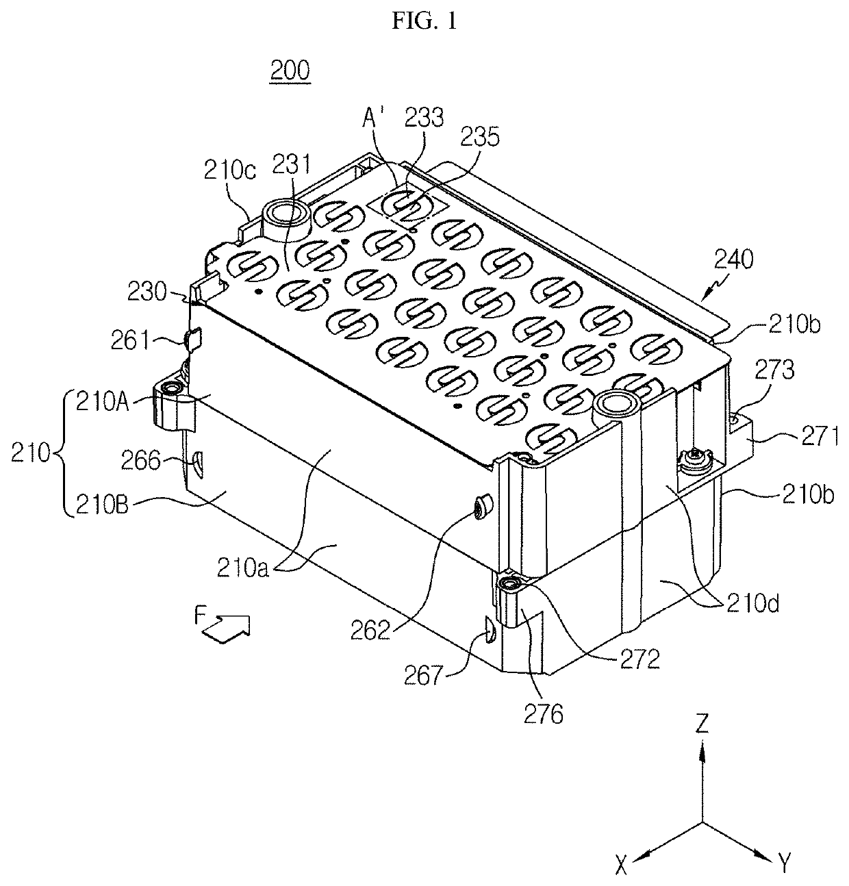
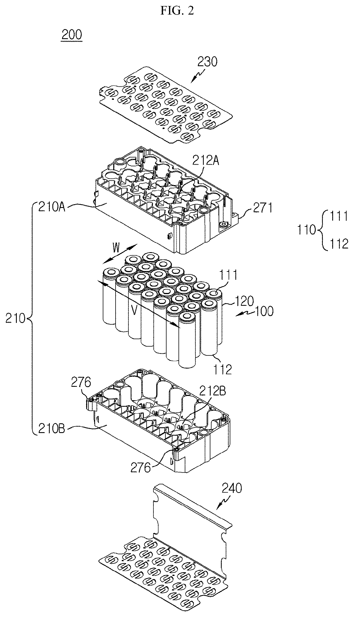
[0044]FIG. 1 is a perspective view schematically showing a battery module according to an embodiment of the present disclosure. FIG. 2 i...


PUM

PropertyMeasurementUnit
widthaaaaaaaaaa
weldabilityaaaaaaaaaa
current lossaaaaaaaaaa

Abstract

Provided are a battery module including a bus bar, whereby weldability may be increased by reducing current loss when welding the bus bar and an electrode terminal of a battery cell, and a battery pack including the battery module. The battery module includes: a plurality of cylindrical battery cells; a module housing; and a bus bar configured to contact the electrode terminals of the plurality of cylindrical battery cells to electrically connect between the plurality of cylindrical battery cells, wherein the bus bar includes: a main body portion that is positioned over or below the plurality of cylindrical battery cells and has a plate shape that is flat in a horizontal direction, wherein at least one coupling opening perforated vertically is formed in the plate shape; and a first connection extension portion and a second connection extension portion that protrude and extend from an internal boundary of the coupling opening in different horizontal directions from each other and have end portions that are electrically connected and fixed to an electrode terminal of one of the plurality of cylindrical battery cells.

Description

TECHNICAL FIELD[0001]The present disclosure relates to a battery module including a bus bar and a battery pack including the battery module, and more particularly, to a battery module including a bus bar, in which weldability between a bus bar and an electrode terminal of a cylindrical battery cell may be increased by reducing current loss when welding the bus bar and the electrode terminal, and a battery pack including the battery module.[0002]The present application claims priority to Korean Patent Application No. 10-2018-0069707 filed on Jun. 18, 2018 in the Republic of Korea, the disclosures of which are incorporated herein by reference.BACKGROUND ART[0003]Recently, demands for portable electronic products, such as laptop computers, video cameras, portable phones, etc. have rapidly increased, and development of electric vehicles, batteries for energy storage, robots, and satellites, etc. has increased, and thus studies on high-performance secondary batteries capable of repetitiv...

Claims


Application Information

Patent Timeline
Patent Type & Authority Patents(United States)
IPC IPC(8): H01M50/502H01M50/20H01M50/572H01M50/531H01M10/04H01M50/213H01M50/503H01M50/505H01M50/516H01M50/522H01M50/586
CPCH01M50/502H01M10/0422H01M50/20H01M50/531H01M50/572H01M2220/10H01M2220/20H01M50/503H01M50/505H01M50/516H01M50/213H01M50/586H01M50/522Y02E60/10Y02P70/50
Inventor PARK, JI-SOOYOON, SEOG-JIN
Owner LG ENERGY SOLUTION LTD
Why Eureka
Try Eureka