Power supply integrated vacuum pump

Active Publication Date: 2022-07-26
SHIMADZU CORP
View PDF14 Cites 0 Cited by
  • Summary
  • Abstract
  • Description
  • Claims
  • Application Information

AI Technical Summary

Benefits of technology

[0003]In the above-described power supply integrated turbo-molecular pump, when the power supply portion is fixed to the pump main body, a defect that part of a power-supply-side line connected to the connector fixed to the pump main body protrudes from a power supply portion housing and is tucked between the pump main body or the connector and the power supply portion housing is easily caused.
[0005]According to the present invention, tucking of a line upon fixing of a power supply portion can be reduced.

Problems solved by technology

In the above-described power supply integrated turbo-molecular pump, when the power supply portion is fixed to the pump main body, a defect that part of a power-supply-side line connected to the connector fixed to the pump main body protrudes from a power supply portion housing and is tucked between the pump main body or the connector and the power supply portion housing is easily caused.

Method used


Image

  • Power supply integrated vacuum pump
  • Power supply integrated vacuum pump
  • Power supply integrated vacuum pump

Examples


Embodiment Construction

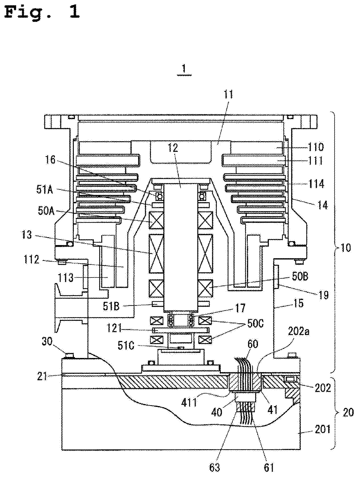
[0014]Hereinafter, a mode for carrying out the present invention will be described with reference to the drawings. FIG. 1 is a sectional view of a schematic configuration of a power supply integrated turbo-molecular pump 1 as one example of a power supply integrated vacuum pump. The power supply integrated turbo-molecular pump 1 illustrated in FIG. 1 is configured such that a pump main body 10 and a power supply portion 20 are integrally fixed to each other with bolts 30.

[0015]The pump main body 10 includes a pump case 14 and a pump base 15 forming a pump housing. In the pump main body 10, a shaft 12 attached to a pump rotor 11 is non-contact supported by magnetic bearings 50A, 50B, 50C provided at the pump base 15. A levitation position of the shaft 12 is detected by radial displacement sensors 51A, 51B and an axial displacement sensor 51C provided at the pump base 15. Note that in a state in which the magnetic bearings are not in operation, the shaft 12 is supported by mechanical ...


PUM


Abstract

A power supply integrated vacuum pump comprises: a pump housing in which a pump rotor is arranged; a power supply housing fixed to an outer surface of the pump housing; a connector configured to connect a pump-housing-side line and a power-supply-housing-side line; and a spacer fixed to the outer surface of the pump housing and having a connector fixing surface to which the connector is fixed.

Description

BACKGROUND OF THE INVENTION1. Technical Field[0001]The present invention relates to a power supply integrated vacuum pump.2. Background Art[0002]Typically, a power supply integrated turbo-molecular pump configured such that a pump main body and a power supply portion are integrated with each other has been known (see, e.g., Patent Literature 1 (JP 2018-184874 A)). In the power supply integrated turbo-molecular pump described in Patent Literature 1, a connector to which a pump-main-body-side line is connected is directly fixed to an outer surface of the pump main body. A power supply portion side is under atmospheric pressure environment, but a pump base side is under vacuum environment. Thus, a hermetic seal connector is used as the connector.SUMMARY OF THE INVENTION[0003]In the above-described power supply integrated turbo-molecular pump, when the power supply portion is fixed to the pump main body, a defect that part of a power-supply-side line connected to the connector fixed to ...

Claims


Application Information

Patent Timeline
Patent Type & Authority Patents(United States)
IPC IPC(8): F04D19/04F04D29/58H01R13/533H02G3/22
CPCH01R13/533F04D19/042F04D29/5806H02G3/22F05B2240/14F05B2240/51F05B2240/57F04D25/06F04D29/5853F04D29/083F04D29/002H01R13/745F04D25/0693F04D19/04F04D29/644
Inventor TANAKA, SHINGO
Owner SHIMADZU CORP
Why Eureka
Try Eureka