Gas-liquid two-phase flow atomizing nozzle

a gas-liquid and atomizing nozzle technology, which is applied in the direction of spray nozzles, insect catchers and killers, animal husbandry, etc., can solve the problems of high cost, drifting, loss, phytotoxicity, and complicated spraying system

Active Publication Date: 2022-08-02
JIANGSU UNIV
View PDF24 Cites 0 Cited by
  • Summary
  • Abstract
  • Description
  • Claims
  • Application Information

AI Technical Summary

Benefits of technology

[0013]To reduce a usage amount of chemical pesticide and improve an operating efficiency of plant-protection pesticide spraying and application machinery and a pesticide utilization rate, the present invention provides a gas-liquid two-phase flow atomizing nozzle. The gas-liquid two-phase flow atomizing nozzle designed by the present invention has the characteristics of a small spray flow rate and a large droplet size, and can effectively improve the pesticide adhesion and anti-drifting performance of the pesticide spraying and application operation while reducing the usage amount of pesticide, to ensure the effect of controlling pests and diseases, thereby achieving a better effect with less chemical pesticide. The present invention not only provides a structure of an atomizing nozzle, but also establishes a relational expression between parameters including the volume median diameter D0.5 of spray droplets of the nozzle, the designed spray flow rate Q and geometrical dimensions of the nozzle, provides design principles for the diameter d1 of the nozzle core air inlet hole, the diameter d2 of the atomizing-body outlet and the diameter d3 of the sleeve air inlet hole, and provides design formulas of the diameter D1 of the jet flow section, the length L1 of the jet flow section, the diffusion angle β of the outlet diffusion section, the maximum inner diameter D2 of the atomizing body mixing chamber and the width b of the air inlet buffering chamber, providing a reference for the accurate control of droplet size and the structural design of the nozzle.
[0061]The beneficial effects of the present invention lie in that the gas-liquid two-phase flow atomizing nozzle designed according to the present invention has the characteristics of a small spray flow rate and a large droplet size, and using the nozzle to spray and apply a chemical pesticide can reduce the amount of pesticide applied, improve the adhesion property of the pesticide liquid, and reduce drifting, thereby achieving a better effect with less chemical pesticide. In addition, internal wear of the nozzle can be reduced, thereby effectively prolonging the service life of the nozzle.

Problems solved by technology

However, external mix nozzles need to be equipped with a liquid pressurizing and air pressurizing means, resulting in a complicated spraying system with high costs, and small-diameter droplets are likely to cause drifting, loss, and phytotoxicity.
However, similar to external mix nozzles, internal-external mix nozzles also need to be equipped with a liquid pressurizing and air pressurizing means, resulting in a complicated spraying system with high costs, and are likely to cause drifting, loss, and phytotoxicity.
However, the existing patented technologies still have the following problems.
Gas-liquid two-phase flow atomizing nozzles currently used in the plant-protection machinery field are all for enhancing the atomizing effect, and the small droplet size and long spraying distance are likely to cause pesticide drifting, loss, and phytotoxicity.
There is no patented technological achievement or literature in the area of design and development of nozzles with large droplet size and small spray flow rate by using the gas-liquid two-phase flow technique to suppress the atomizing effect of the nozzle.
Existing patented technologies related to the gas-liquid two-phase flow fail to establish a relational expression between the spray droplet size of the nozzle, the spray flow rate, the spray medium characteristics and geometrical dimension parameters of the nozzle, and lack methods for designing and controlling the droplet size.
Existing relevant patented technologies mainly describe the constituents, structural features, and flow path shape of the nozzle, and provide some structural solutions, but cannot provide technical support for the specific dimension design of the nozzle for nozzle products with detailed design conditions regarding the volume median diameter of spray droplets, the designed spray flow rate, and the medium characteristics.

Method used


Image

  • Gas-liquid two-phase flow atomizing nozzle
  • Gas-liquid two-phase flow atomizing nozzle
  • Gas-liquid two-phase flow atomizing nozzle

Examples


Embodiment Construction

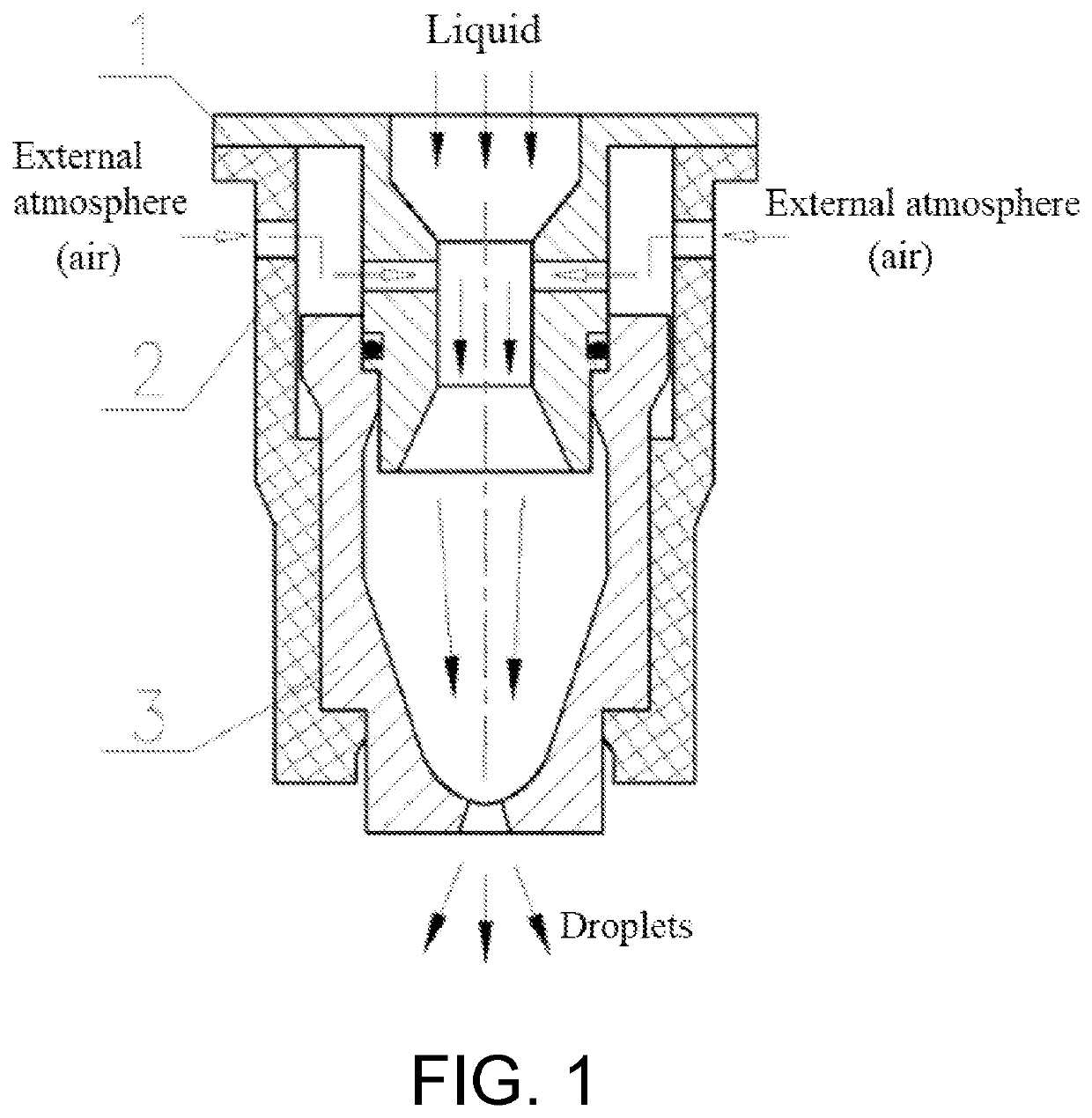
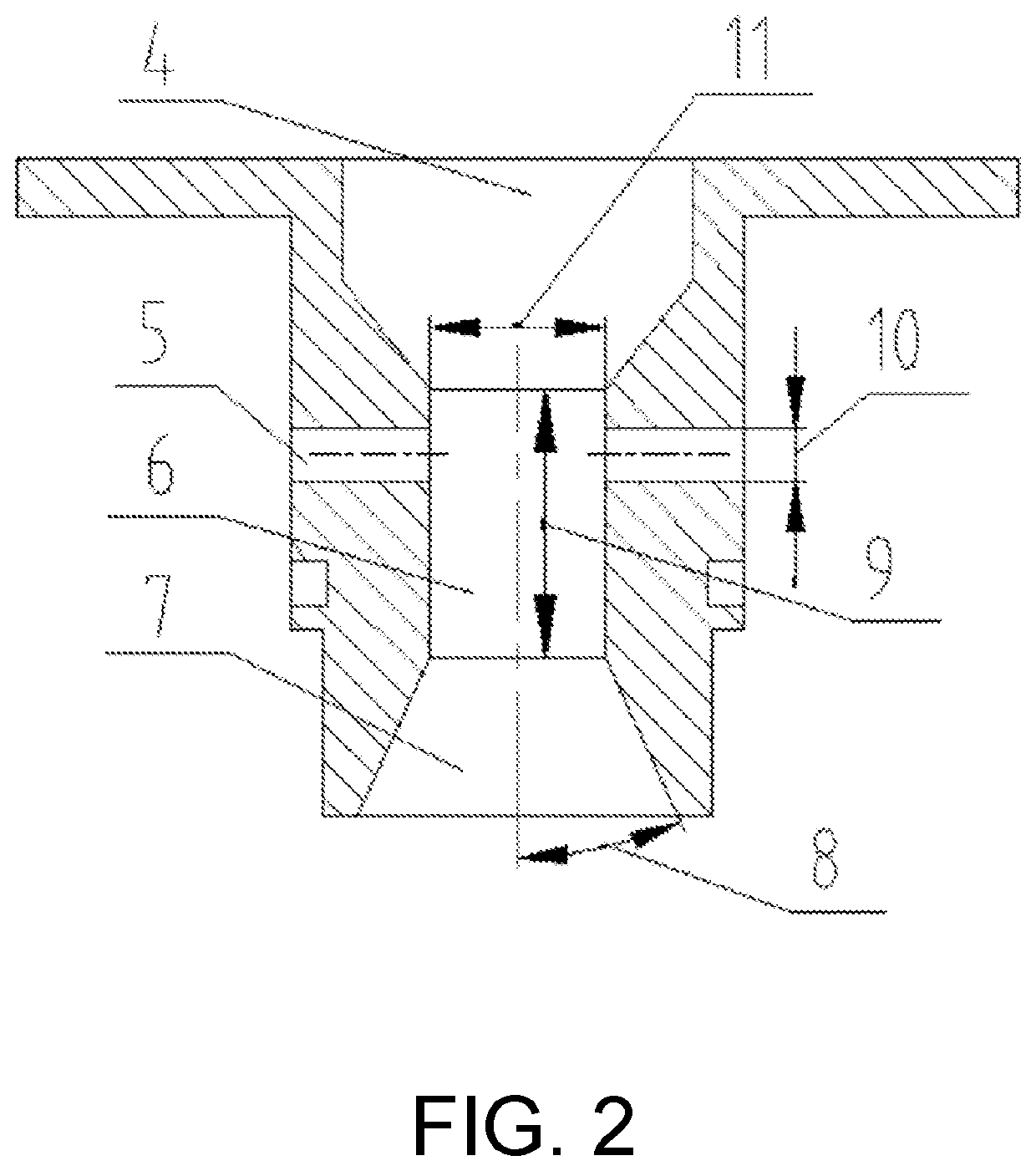
[0067]FIG. 1 to FIG. 4 together determine the structure and geometrical dimensions of a nozzle according to this embodiment, which is a gas-liquid two-phase flow atomizing nozzle having an axisymmetric structure, and includes a nozzle core 1, an outer sleeve 2, and an atomizing body 3. An inner cavity of the nozzle core 1 consists of an inlet tapered section 4, a jet flow section 6, and an outlet diffusion section 7. The outlet diffusion section 7 is in communication with an atomizing body mixing chamber 16. A nozzle core air inlet hole 5 and a sleeve air inlet hole 12 are respectively provided on a wall surface of the nozzle core 1 and a wall surface of the outer sleeve 2, so that the jet flow section 6 in the inner cavity of the nozzle core 1 is in communication with external atmosphere through the nozzle core air inlet hole 5, an air inlet buffering chamber 13, and the sleeve air inlet hole 12. Liquid flows along a central axis of the nozzle, and is atomized after sequentially fl...


PUM


Abstract

A gas-liquid two-phase flow atomizing nozzle includes a nozzle core, an outer sleeve, and an atomizing body. An inner cavity of the nozzle core consists of an inlet tapered section, a jet flow section, and an outlet diffusion section. The outlet diffusion section of the nozzle core is connected to an atomizing body mixing chamber. The jet flow section of the nozzle core is in communication with external atmosphere through a core air inlet hole, an air inlet buffering chamber, and a sleeve air inlet hole.

Description

BACKGROUNDTechnical Field[0001]The present invention relates to a gas-liquid two-phase flow atomizing nozzle, and specifically to structural features of an internal mix gas-liquid two-phase flow atomizing nozzle. The nozzle is applicable to the field of pesticide spraying and application using plant-protection machinery in orchards and facility agriculture.Description of Related Art[0002]In the technical field of pesticide spraying and application using plant-protection machinery in agriculture, gas-liquid two-phase flow atomizing nozzles are widely applied to the spraying of various chemical pesticides. A pesticide liquid is atomized by the gas-liquid two-phase flow atomizing nozzle into fine spray droplets to be sprayed on the plant surface. At present, there are mainly three types of gas-liquid two-phase flow atomizing nozzles: internal mix type, external mix type, and internal-external mix type. For internal mix nozzles, liquid and gas form a gas-liquid two-phase flow inside the...

Claims


Application Information

Patent Timeline
Patent Type & Authority Patents(United States)
IPC IPC(8): B05B7/04
CPCB05B7/0425B05B7/0458B05B1/048A01M7/00B05B1/02
Inventor OU, MINGXIONGZANG, SHUAIZHANG, CHUANJIA, WEIDONGZHOU, HUITAO
Owner JIANGSU UNIV
Why Eureka
Try Eureka