
System and method for leak detection using a manifold assembly and model monitor cylinder

Active Publication Date: 2022-08-02
LEE KENNETH
View PDF17 Cites 0 Cited by
  • Summary
  • Abstract
  • Description
  • Claims
  • Application Information

AI Technical Summary

Benefits of technology

The patent is about a system and method for quickly detecting water leaks in plumbing systems that uses flexible materials and components. The system includes a static device (known as a "water widget"), an expansion gauge, a mathematical model, and a software program. The system can accurately detect the flow rate of water leaks in real-time, making it easier to locate and fix leaks quickly. This technology helps to prevent damage and reduce costs associated with water leaks in plumbing systems.

Problems solved by technology

Residential plumbing systems typically have many components, such as joints, valves, and spigots which are prone to leaks.
Many possible failure points exist in these components, many of which are not visible or accessible.
As a result, leaks often arise which may go unrepaired for extended periods of time causing extensive damage.
Determining whether or not a water leak exists and then finding the leakage rate in a plumbing system can be a very complex problem.
As a result, it is difficult to accurately determine the flow rate of a leak in a system which utilizes flexible materials or components.
The prior art has attempted to address these problems, but all have fallen short.
But the method of monitoring a city water meter is incapable of locating small leaks because of the extended period of time required.
Further, the method of monitoring a city water meter fails to account for the problem of leak rate variation due to flexible materials.
However, Mess requires permanent installation of a device.
Furthermore, Mess does not account for flexible components or material expansion.
However, Farkas does not disclose a method for determining the flow rate of a leak and does not account for flexible components or material expansion.
However, Halimi does not disclose an accurate means of measuring the leak flow rate.
As a result, the prior art has failed to provide an adequate and simple means for detecting leaks and calculating leak flow rate in modern plumbing systems in residential structures.

Method used


Image

  • System and method for leak detection using a manifold assembly and model monitor cylinder
  • System and method for leak detection using a manifold assembly and model monitor cylinder
  • System and method for leak detection using a manifold assembly and model monitor cylinder

Examples


Embodiment Construction

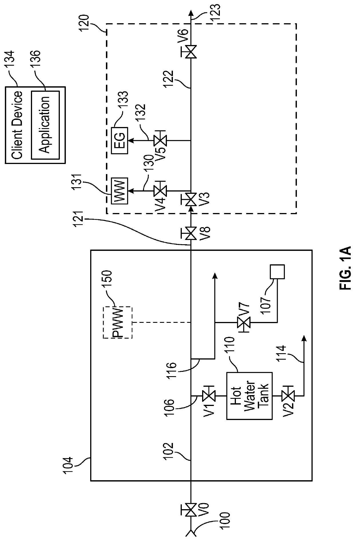
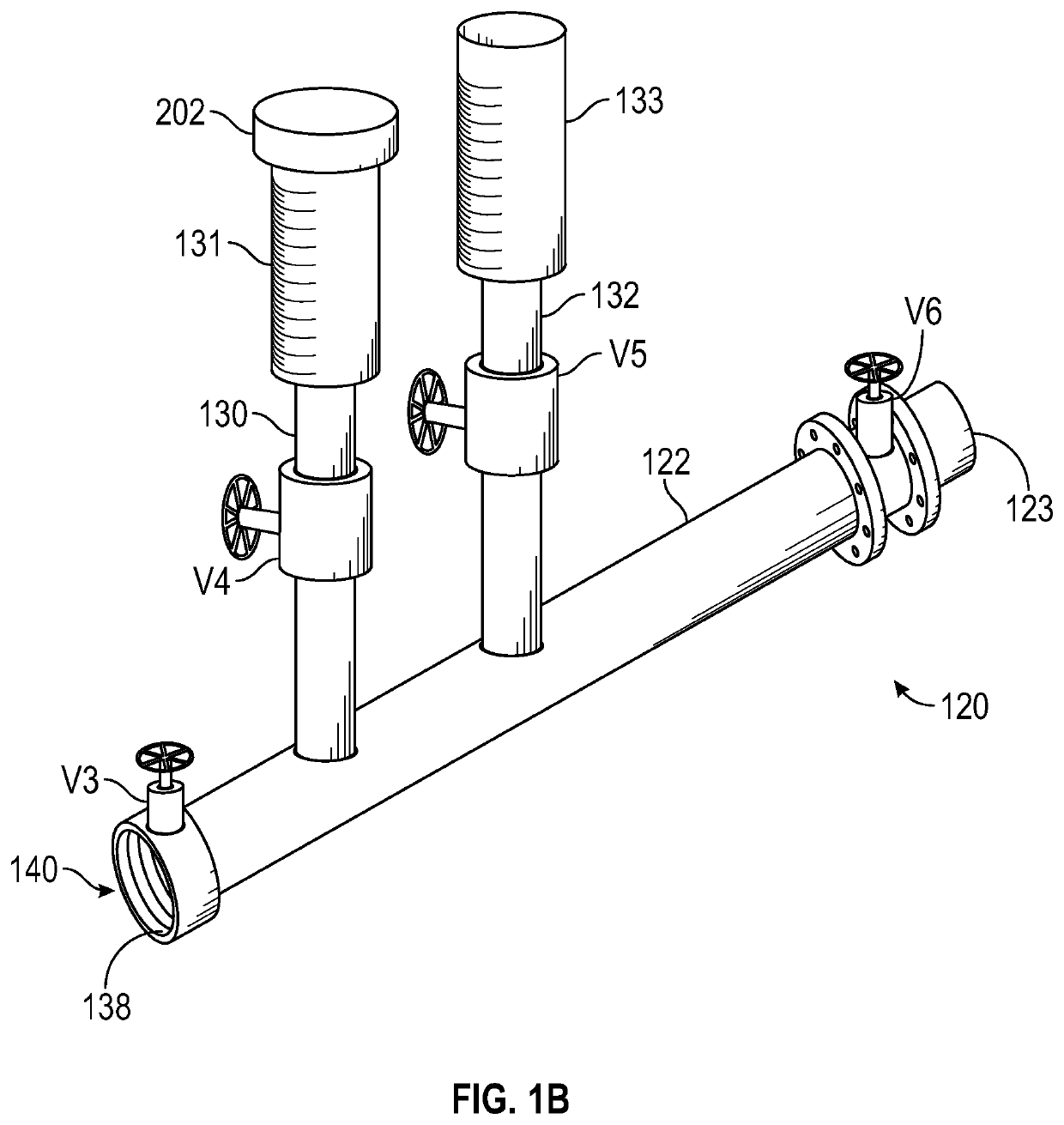
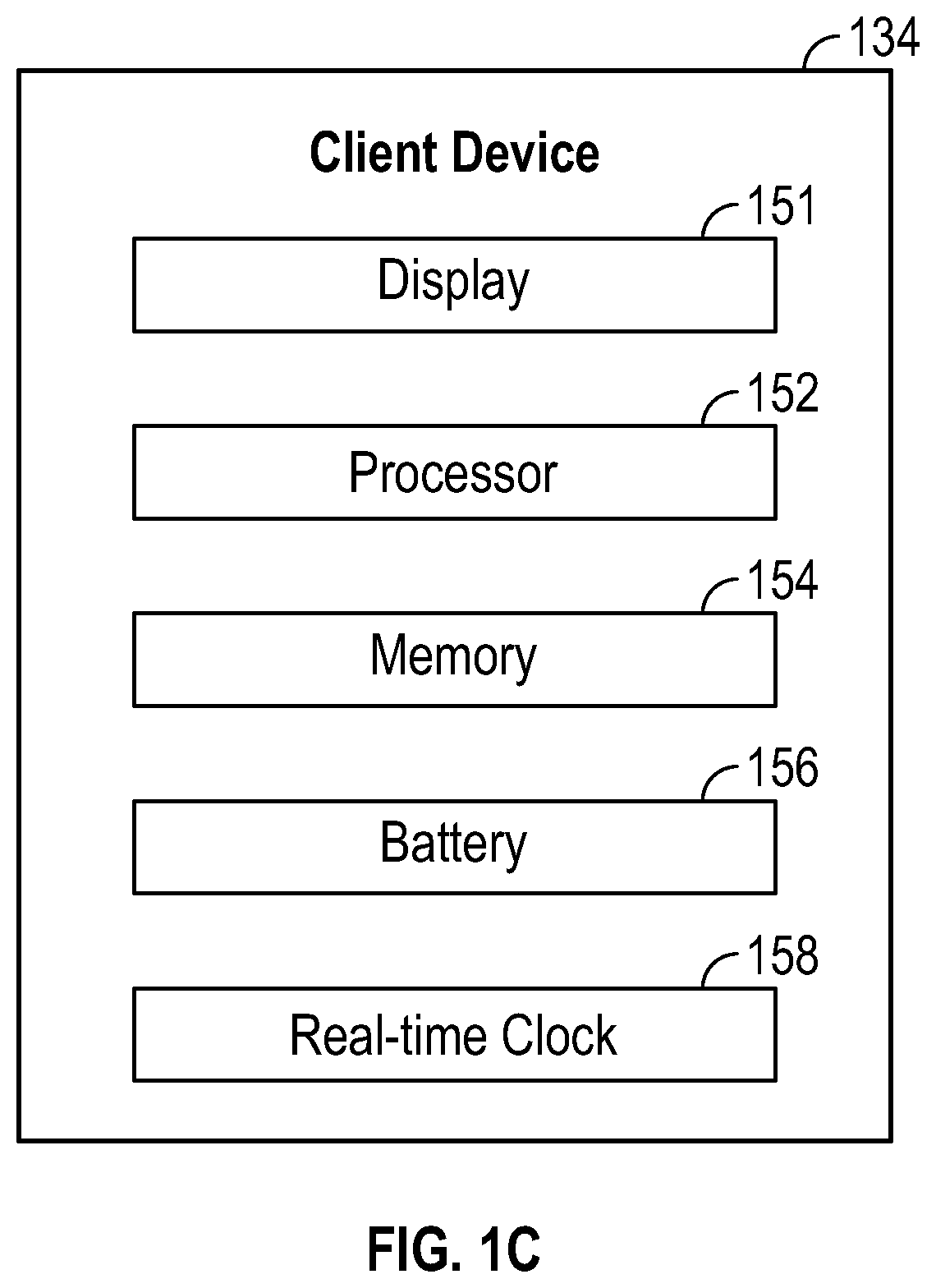
[0028]Referring then to FIG. 1A, a preferred leak detection system will be described. The leak detection system is generally comprised of client device 134, and manifold assembly 120. Manifold assembly 120 includes manifold 122, water widget device (“WW”) 131, and expansion gauge (“EG”) 133. WW 131 and EG 133 may both be considered monometer type monitoring cylinders. Client device 134 is preferably a mobile computing device, such as a smart phone or tablet, and includes application 136. Application 136 includes a timer. Various water levels observed from WW 131 and EG 133 during the method are input into application 136 to calculate the leak rate, as will be further described.

[0029]Manifold 122 is connected to residential structure 104. Structure 104 and the plumbing system described in it are just examples. One of skill will recognize that many other structures and variations of plumbing systems are possible and can be analyzed for leaks with the system and method disclosed.

[0030]...


PUM


Abstract

The present invention is a system and method for detecting water leaks and calculating leak rates. The system is comprised of a “water widget”, a manifold assembly, and “expansion gauge”, and two flexible hoses. The system is connected to an existing plumbing system and the plumbing system is pressurized to determine the size of a “phantom water widget”. The “phantom water widget” is used to mathematically represent the additional water in a pressurized plumbing system due to the expansion of certain materials (e.g., PEX pipes). The “phantom water widget” and the “water widget” are then used to determine the leak rate. The invention is further comprised of a mobile phone application which used to calculate the leak rate based on data derived from the system.

Description

CROSS-REFERENCE TO RELATED APPLICATIONS[0001]This application claims priority benefit from U.S. Provisional Application No. 63 / 207,853, filed on Mar. 25, 2021. The patent application identified above is incorporated here by reference in its entirety to provide continuity of disclosure.FIELD OF THE INVENTION[0002]The present invention relates to water leak detection methods.BACKGROUND OF THE INVENTION[0003]Residential plumbing systems typically have many components, such as joints, valves, and spigots which are prone to leaks. Many possible failure points exist in these components, many of which are not visible or accessible. As a result, leaks often arise which may go unrepaired for extended periods of time causing extensive damage. Determining whether or not a water leak exists and then finding the leakage rate in a plumbing system can be a very complex problem.[0004]To complicate matters, most modern plumbing systems include flexible components, such as water heaters, which vary i...

Claims


Application Information

Patent Timeline
IPC IPC(8): G01M3/28
CPCG01M3/28
Inventor LEE, KENNETH
Owner LEE KENNETH
Learn More