Apparatus for detecting a modulation transfer function and centering of an optical system

a technology of modulation transfer function and optical system, applied in the direction of optical apparatus testing, optical axis determination, instruments, etc., can solve the problems of undetectable optical system optical properties and state cannot be achieved, and achieve the effect of high quality

Active Publication Date: 2021-03-09
TRIOPTICS GMBH
View PDF16 Cites 0 Cited by
  • Summary
  • Abstract
  • Description
  • Claims
  • Application Information

AI Technical Summary

Benefits of technology

[0010]Advantageously, both the imaging performance as well as the centering of the optical system can be measured with the apparatus according to the invention in particular simultaneously by means of one or more, furthermore simultaneously performed, MTF measurement(s). In particular, this allows to perform a subsequent fine adjustment to optimize the imaging performance based on a rough adjustment based on the measuring results of the centering measuring apparatus. Furthermore, the combination of an MTF measurement and centering measuring apparatus is in particular suitable for mass production since a plurality of parameters of the optical system can be detected quickly and efficiently.
[0015]With the aid of the MTF measuring apparatus arranged off-axis, MTF measurements can be carried out at various field points in the field of view of the optical system. The MTF measuring apparatus can be easily arranged off-axis. The centering measuring apparatus is however advantageously arranged on-axis. By the combination of an MTF measuring apparatus that is arranged off-axis and a centering measuring apparatus being arranged on-axis, a particularly compact apparatus can be presented.
[0042]In embodiments in which the graticule provides a test pattern for the MTF measurement and a point light source for the centering measurement, in particular the test pattern on the graticule and the pinhole aperture in the graticule are optionally illuminated with different light sources which are designed to be sequentially switchable. This makes it possible for example to measure the wavefront without interference.
[0050]With such a method, it is possible to improve / optimize the optical imaging quality of the optical system based on the results of the centering measurement. Subsequently performing an MTF measurement makes it possible, for example within the context of quality assurance, to quantify the optical imaging quality of the optical system.
[0056]With the assistance of this method, it is for example possible to produce an optical system of a very high quality since it is checked and optimized during the production process with regard to its centering.

Problems solved by technology

In real optical systems, this state can however not be achieved due to production and installation tolerances.
If the distances between the centers of curvature and the reference axis are too large, the optical properties of the optical system undesirably degrade.

Method used


Image

  • Apparatus for detecting a modulation transfer function and centering of an optical system
  • Apparatus for detecting a modulation transfer function and centering of an optical system
  • Apparatus for detecting a modulation transfer function and centering of an optical system

Examples


Embodiment Construction

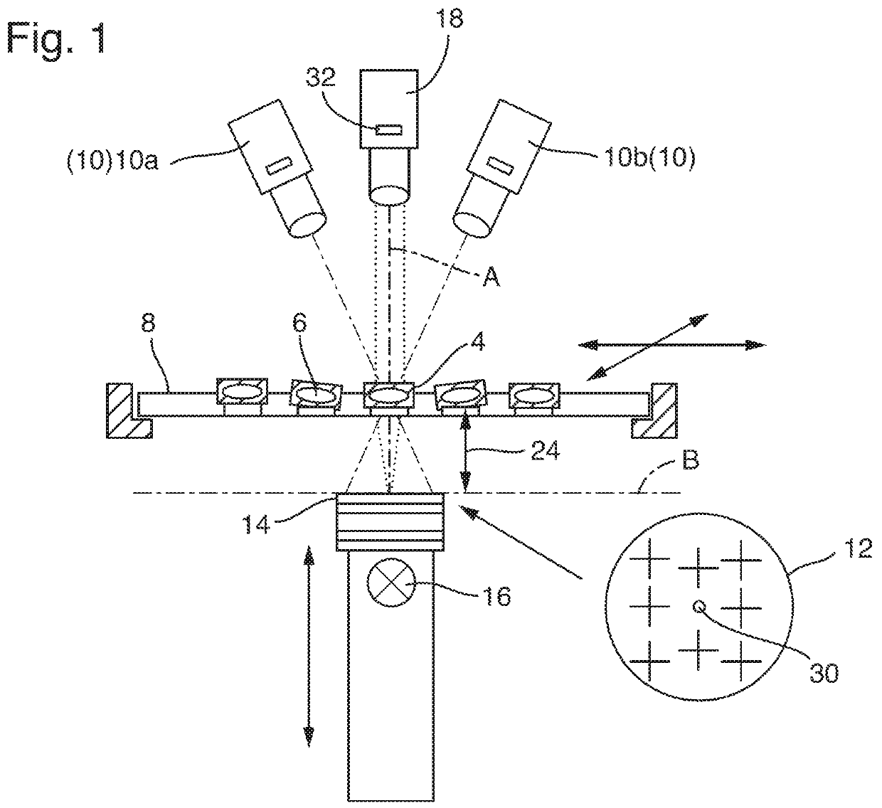
[0067]FIG. 1 shows a schematically simplified side view of an apparatus 2 for detecting imaging quality of an optical system 4. For example, the apparatus 2 is configured to test and / or optimize a plurality of optical systems 4 with regard to their imaging quality, of which only a few are provided with reference signs for reasons of clarity. The optical systems 4 moreover comprise e.g. only a single optical element, i.e., a lens 6. The apparatus 2 shown in FIG. 1 is only provided for example for a mass test of optical systems 4. For this purpose, the optical systems 4 such as camera objectives are seated on a carrier 8 that, as indicated with arrows, can be moved on a plane. Accordingly, the individual optical systems 4 can be checked sequentially in rapid sequence.

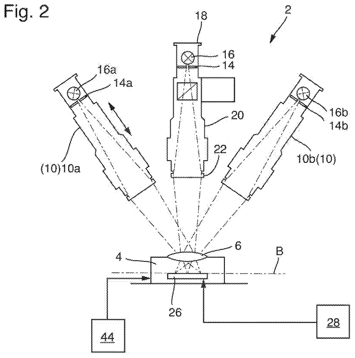
[0068]The apparatus 2 comprises an MTF measuring apparatus 10 that for example comprises the two measuring apparatus 10a and 10b arranged off-axis. The MTF measuring apparatus 10 is configured to detect a modulation trans...


PUM

PropertyMeasurementUnit
imaging qualityaaaaaaaaaa
axes of symmetryaaaaaaaaaa
distancesaaaaaaaaaa

Abstract

The invention relates to an apparatus (2) for detecting imaging quality of an optical system (4) with at least one lens (6) or lens group. The apparatus (2) includes an MTF measuring apparatus (10) for measuring a modulation transfer function at a plurality of field points in the field of view of the optical system (4), and a centering measuring apparatus (18) for measuring a centered state of the optical system (4). Furthermore, the invention relates to a method for detecting imaging quality of an optical system (4) having such a apparatus (2).

Description

CROSS-REFERENCE TO RELATED APPLICATIONS[0001]This application claims priority to EP 17 174 143.2, filed Jun. 2, 2017.BACKGROUND OF INVENTIONField of Invention[0002]The invention relates to an apparatus for detecting imaging quality of an optical system with at least one lens or lens group. Furthermore, the invention relates to a method for detecting imaging quality of an optical system, comprising at least one lens or lens group, having such an apparatus.Brief Description of Related Art[0003]In the production of high-quality multi-lens optical systems, the individual lenses must be aligned very precisely relative to each other. Also in the production of camera modules as for example described in Brodie et al., Pub. No. US 2016 / 0334600 A1, it is necessary to correctly align and center the optical elements relative to each other and with reference to the image sensor.[0004]To perform a correct alignment of the lenses in an optical system, it is necessary to establish a position of the...

Claims


Application Information

Patent Timeline
Patent Type & Authority Patents(United States)
IPC IPC(8): G01M11/02G02B7/00
CPCG01M11/0292G01M11/0207G01M11/0221G02B7/005G01M11/0214
Inventor DUMITRESCU, EUGENLANGEHANENBERG, PATRIKERICHSEN, IRISBAI, ALEXANDERZILIAN, SIMONRUPRECHT, AIKO
Owner TRIOPTICS GMBH
Why Eureka
Try Eureka