Method and device for detecting lanes, driver assistance system and vehicle

a technology of driver assistance system and detecting lanes, applied in the direction of image analysis, image enhancement, instruments, etc., can solve the problems of reduced evaluation speed, increased energy consumption, and relatively high computation cos

Active Publication Date: 2022-08-16
CONTINENTAL TEVES AG & CO OHG +1
View PDF19 Cites 0 Cited by
  • Summary
  • Abstract
  • Description
  • Claims
  • Application Information

AI Technical Summary

Benefits of technology

[0007]It is therefore an object of the present invention to make possible a rapid and precise detection of lanes.
[0013]The invention provides a two-stage detection of lanes. During a first stage, the camera image is analyzed by means of preferably traditional methods for detecting features and feature points are determined, which correspond to regions of possible lane boundaries. During this first step, less relevant regions, i.e. those regions in which in all probability no lane boundaries are to be expected, are already eliminated in a coarse evaluation. This reduces the computational cost during the further processing of the data.
[0016]The invention consequently preferably combines traditional methods with the use of neural networks. However, due to the pre-filtering, only specific regions of the camera image have to be analyzed by means of the neural network and a total evaluation of all of the pixels can be dispensed with. As a result, the lane detection can be performed quickly and efficiently. At the same time, the high detection accuracies of the neural networks can be fully utilized.
[0017]In order to prevent lane boundaries not being detected, the thresholds which have to be exceeded in order to detect a pixel as a feature point are preferably set relatively low. The resulting false identifications are subsequently filtered out again by means of the neural network. If Sobel filters are exclusively used, the thresholds are typically selected in such a way that as few misidentifications as possible occur. As a result, low-contrast lane boundaries are not detected however. Thanks to the two-stage method according to the invention, no such compromise has to be made and the detection accuracy is higher.

Problems solved by technology

However, since detected images are typically evaluated by means of neural networks pixel by pixel, the computational cost is relatively high, resulting in an increased energy consumption and a reduced evaluation speed.

Method used


Image

  • Method and device for detecting lanes, driver assistance system and vehicle
  • Method and device for detecting lanes, driver assistance system and vehicle
  • Method and device for detecting lanes, driver assistance system and vehicle

Examples


Embodiment Construction

[0038]Further possible configurations, further developments and implementations of the invention also comprise combinations of features of the invention described above or below with respect to the embodiment examples, which are not explicitly indicated.

[0039]The appended drawings are intended to convey a further understanding of the embodiments of the invention. They illustrate embodiments and, in connection with the description, serve to explain the principles and concepts of the invention. Other embodiments and many of the indicated advantages are set out with respect to the drawings. The same reference numerals indicate the same or similarly acting components.

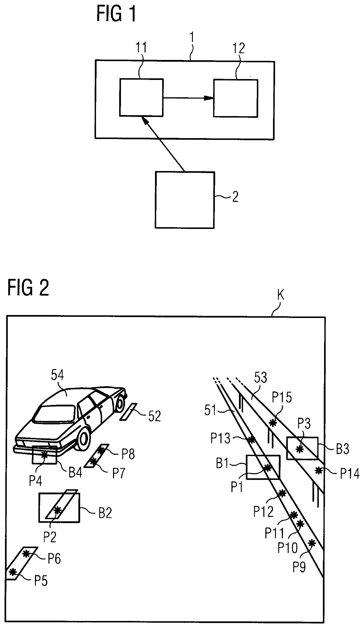
[0040]FIG. 1 shows a schematic block diagram of a device 1 for detecting lanes.

[0041]The device 1 comprises an interface 11 which is configured to receive and output data wirelessly or via a wired connection. In particular, the interface 11 receives camera data and transfers said data to a computing apparatus 12 of the devi...


PUM


Abstract

A method of detecting lanes includes the steps: capturing (S1) a camera image (K) of a vehicle environment by a camera device (2) of a vehicle (5); determining (S2) feature points (P1 to P15) in the camera image (K), which feature points correspond to regions of possible lane boundaries (M1, M2); generating (S3) image portions of the captured camera image (K) respectively around the feature points (P1 to P15); analyzing (S4) the image portions using a neural network to classify the feature points (P1 to P15); and determining (S5) lanes in the vehicle environment taking account of the classified feature points (P1 to P15).

Description

FIELD OF THE INVENTION[0001]The invention relates to a method for detecting lanes, a device for detecting lanes, a driver assistance system, and a vehicle.BACKGROUND INFORMATION[0002]Driver assistance systems produce a model of the vehicle surroundings based on a plurality of sensor data. In addition to detecting obstacles and further road users, the detection of lanes is particularly relevant. By establishing the vehicle's movement in the lanes, the driver can be given an early warning in the event of the vehicle unintentionally leaving a lane. Driver assistance systems can additionally support the driver with remaining in a particular lane or can steer the vehicle autonomously along the lane.[0003]The lanes are usually detected by establishing the lane boundaries, a term used in particular to denote lane markings and curbsides. The printed publication DE 10 2015 209467 A1 discloses a method of estimating lanes using feature vectors which are established independently of each other...

Claims


Application Information

Patent Timeline
Patent Type & Authority Patents(United States)
IPC IPC(8): G06K9/00G06V20/56G06T7/73G06T7/13G06N3/08G06V10/44
CPCG06V20/588G06N3/08G06T7/13G06T7/73G06V10/443G06T2207/20024G06T2207/20084G06T2207/30256G06V10/44G06V10/454
Inventor BAYER, CHRISTOPHERHELLER, CLAUDIOLOY, CLAUDIAABRAMOV, ALEXEY
Owner CONTINENTAL TEVES AG & CO OHG
Why Eureka
Try Eureka