
Apparatus for detecting a modulation transfer function and centering of an optical system
a technology of modulation transfer function and optical system, which is applied in the direction of optical apparatus testing, optical axis determination, instruments, etc., can solve the problems of undetectable optical system optical properties and inability to achieve the state, and achieve the effect of reducing the force for centering measuremen
- Summary
- Abstract
- Description
- Claims
- Application Information
AI Technical Summary
Benefits of technology
Problems solved by technology
Method used
Image

Examples
Embodiment Construction
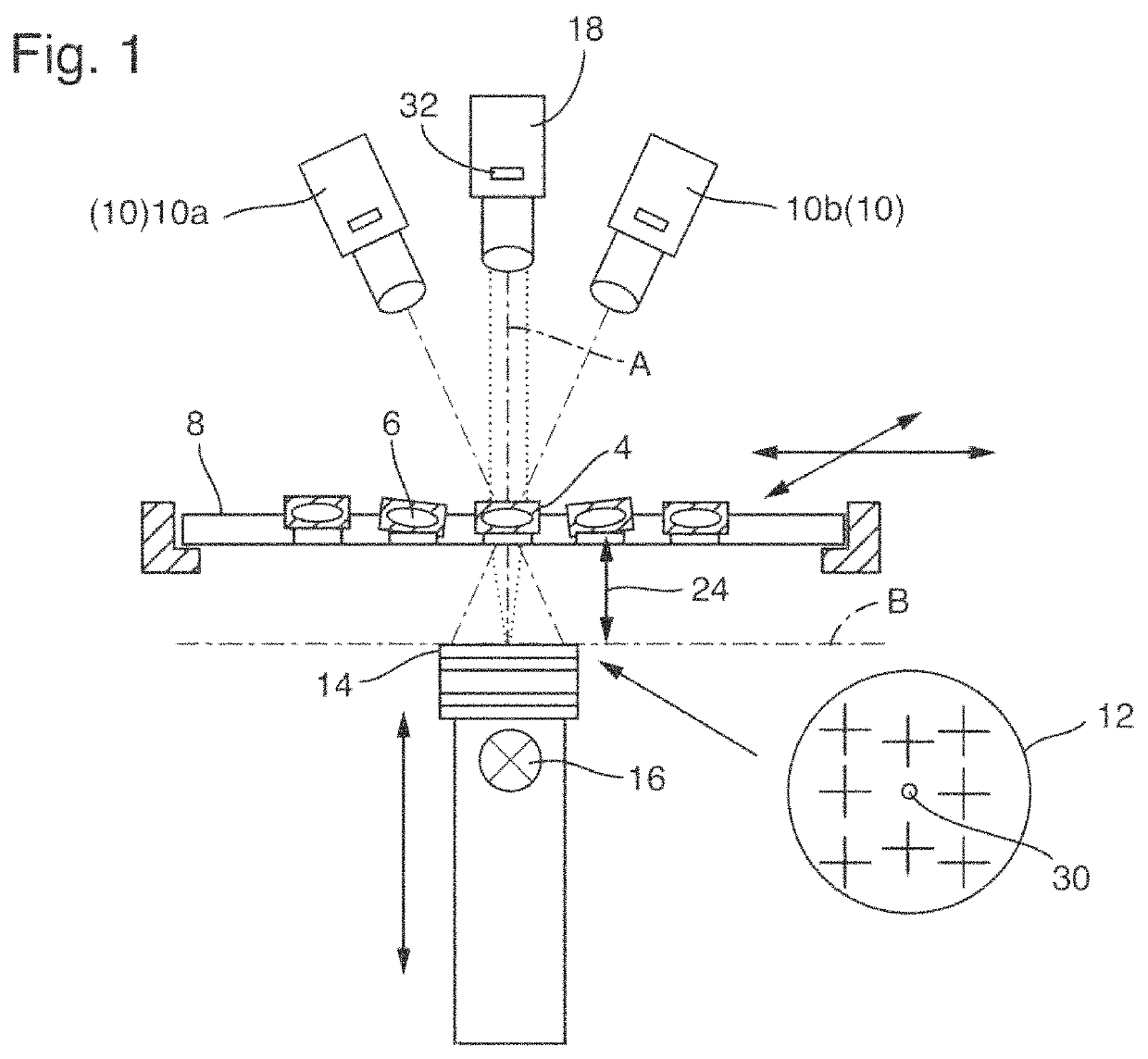
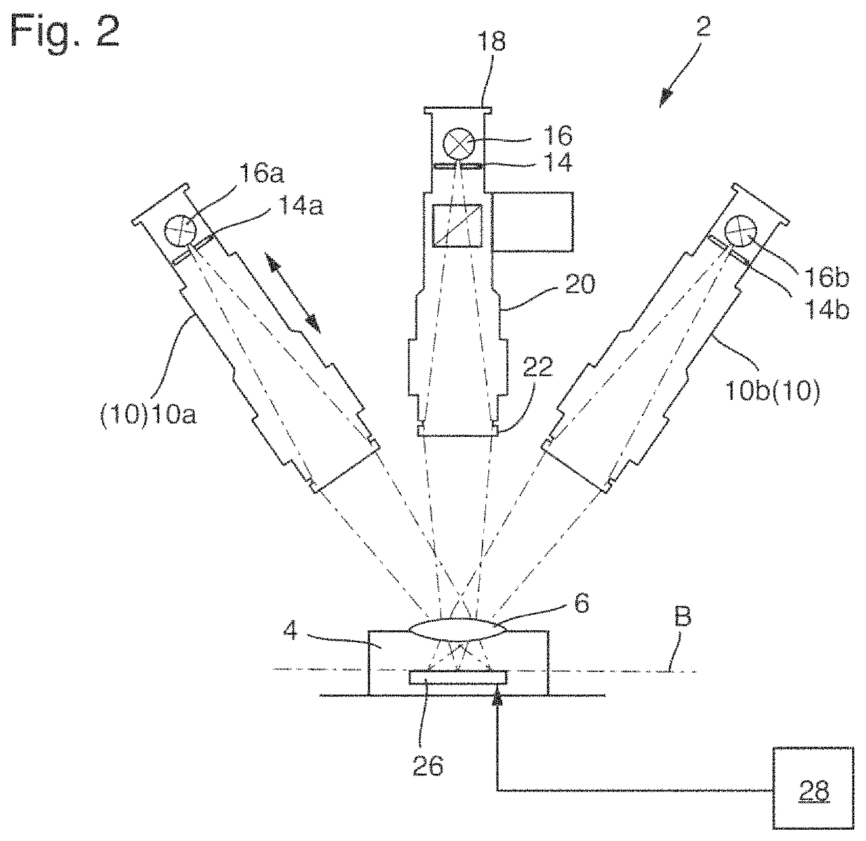
[0071]FIG. 1 shows a schematically simplified side view of an apparatus 2 for detecting imaging quality of an optical system 4. For example, the apparatus 2 is configured to test and / or optimize a plurality of optical systems 4 with regard to their imaging quality, of which only a few are provided with reference signs for reasons of clarity. The optical systems 4 moreover comprise e.g. only a single optical element, i.e., a lens 6. The apparatus 2 shown in FIG. 1 is only provided for example for a mass test of optical systems 4. For this purpose, the optical systems 4 such as camera objectives are seated on a carrier 8 that, as indicated with arrows, can be moved on a plane. Accordingly, the individual optical systems 4 can be checked sequentially in rapid sequence.
[0072]The apparatus 2 comprises an MTF measuring apparatus 10 that for example comprises the two measuring apparatus 10a and 10b arranged off-axis. The MTF measuring apparatus 10 is configured to detect a modulation trans...
PUM
| Property | Measurement | Unit |
|---|---|---|
| imaging quality | aaaaa | aaaaa |
| axes of symmetry | aaaaa | aaaaa |
| distances | aaaaa | aaaaa |
Abstract
Description
Claims
Application Information