Camera calibration device and camera calibration method

a calibration device and camera technology, applied in the direction of mechanical measuring arrangements, instruments, image enhancement, etc., can solve the problems of significant labor and cost, difficult to apply the technology of patent document 1 thereto, etc., and achieve the effect of easy calibration of a relationship

Active Publication Date: 2022-08-02
FANUC LTD
View PDF17 Cites 0 Cited by
  • Summary
  • Abstract
  • Description
  • Claims
  • Application Information

AI Technical Summary

Benefits of technology

[0012]An object of the present invention is to provide a camera calibration device and a camera calibration method in which a calibration instrument is arranged in an arbitrary position of a machine tool in an arbitrary posture and in which thus it is possible to easily calibrate a relationship between a machine coordinate system set on the machine tool and a camera coordinate system of a camera installed in the machine tool.
[0018]According to the present invention, a calibration instrument is arranged in an arbitrary position of a machine tool in an arbitrary posture, and thus it is possible to easily calibrate a relationship between a machine coordinate system set on the machine tool and an image coordinate system of a camera installed in the machine tool.

Problems solved by technology

However, when a table can be only moved parallel to the directions of the X and Y axes or is fixed to a machine tool, that is, when the degree of flexibility is low, it is difficult to apply the technology of patent document 1 thereto.
On the other hand, although patent document 2 can be applied to machine tools such as a table movable-type three-axis machine and a movable-type three-axis machine in which only a spindle can be moved, a calibration instrument of the imaging target member or the like for calibration and a jig for fixing the calibration instrument to a table or the like are needed, with the result that significant labor and cost are needed.

Method used


Image

  • Camera calibration device and camera calibration method
  • Camera calibration device and camera calibration method
  • Camera calibration device and camera calibration method

Examples


first embodiment

Variation 2 of First Embodiment

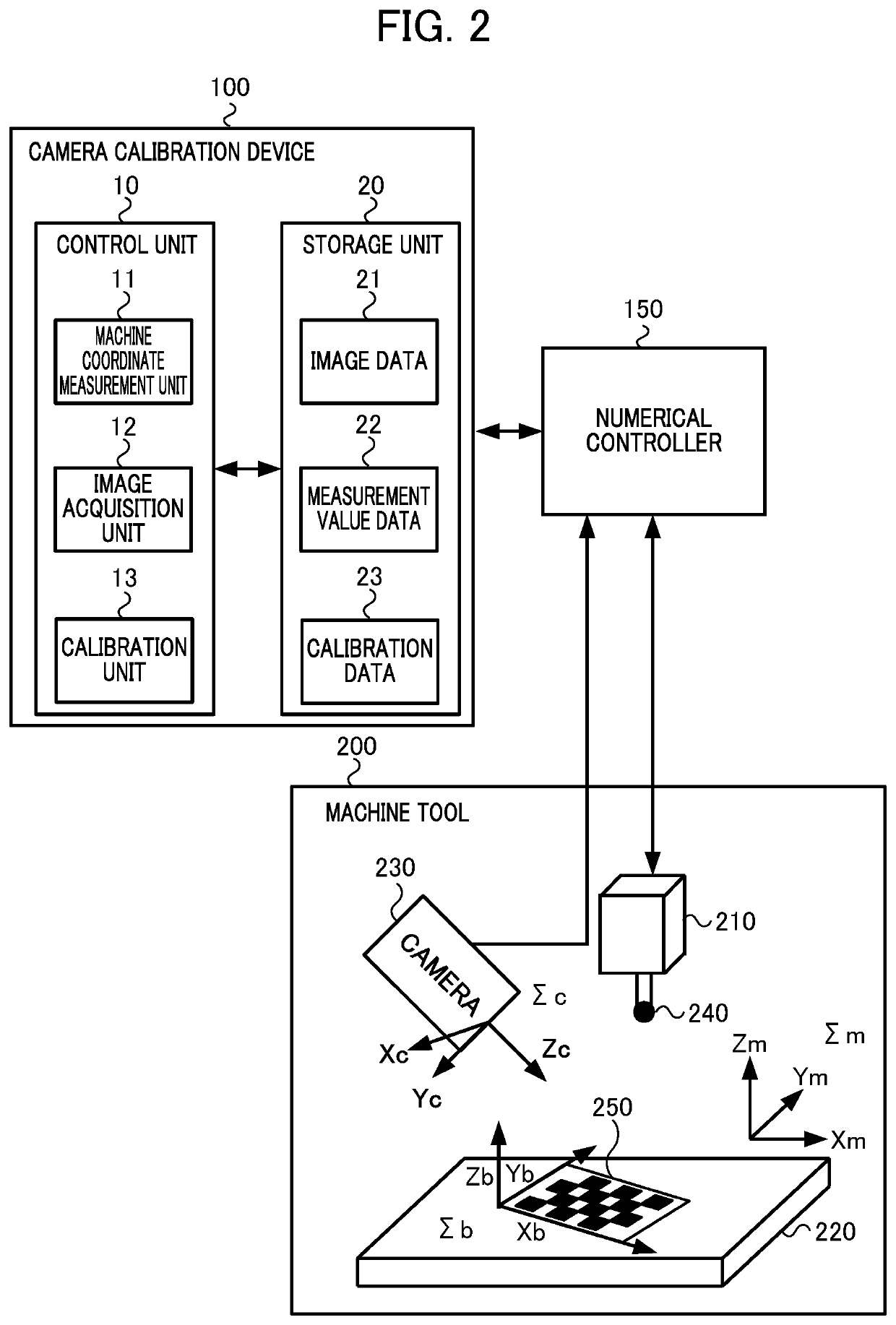
[0119]Although in the camera calibration device 100 according to the first embodiment, an XmYm plane in the machine coordinate system Σm and an XbYb plane in the checkerboard coordinate system Σb are not necessarily parallel to each other, and thus the table 220 is moved in each of the directions of the Xm axis and the Ym axis, there is no limitation to this configuration. For example, as a variation 2 of the first embodiment, in the camera calibration device 100, when the XmYm plane in the machine coordinate system Σm and the XbYb plane in the checkerboard coordinate system Σb are parallel to each other, the table 220 may be moved only in any one of the directions of the Xm axis and the Ym axis.

[0120]In this case, the camera calibration device 100 can directly determine a straight line between the feature point A and the feature point A1 on a plane obtained by performing reverse transformation on the internal parameter K and the posture Rc with respec...

second embodiment

Variation 2 of Second Embodiment

[0166]Although the camera calibration device 100A according to the second embodiment detects a plurality of feature points D, E and F on the table 220, there is no limitation to this configuration. For example, as a variation 2 of the second embodiment, when the XmYm plane in the machine coordinate system Σm and an XtYt plane in the table coordinate system Σt are parallel to each other, the camera calibration device 100A may use only one feature point.

third embodiment

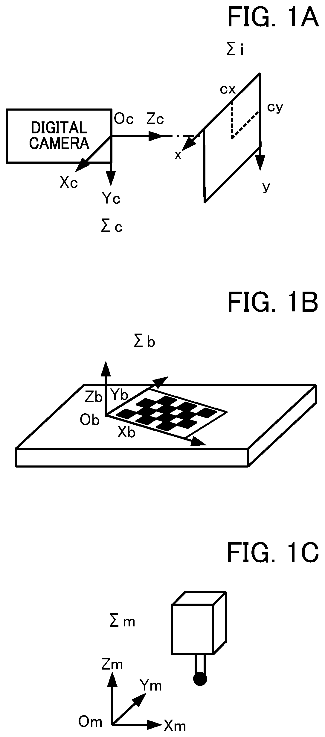
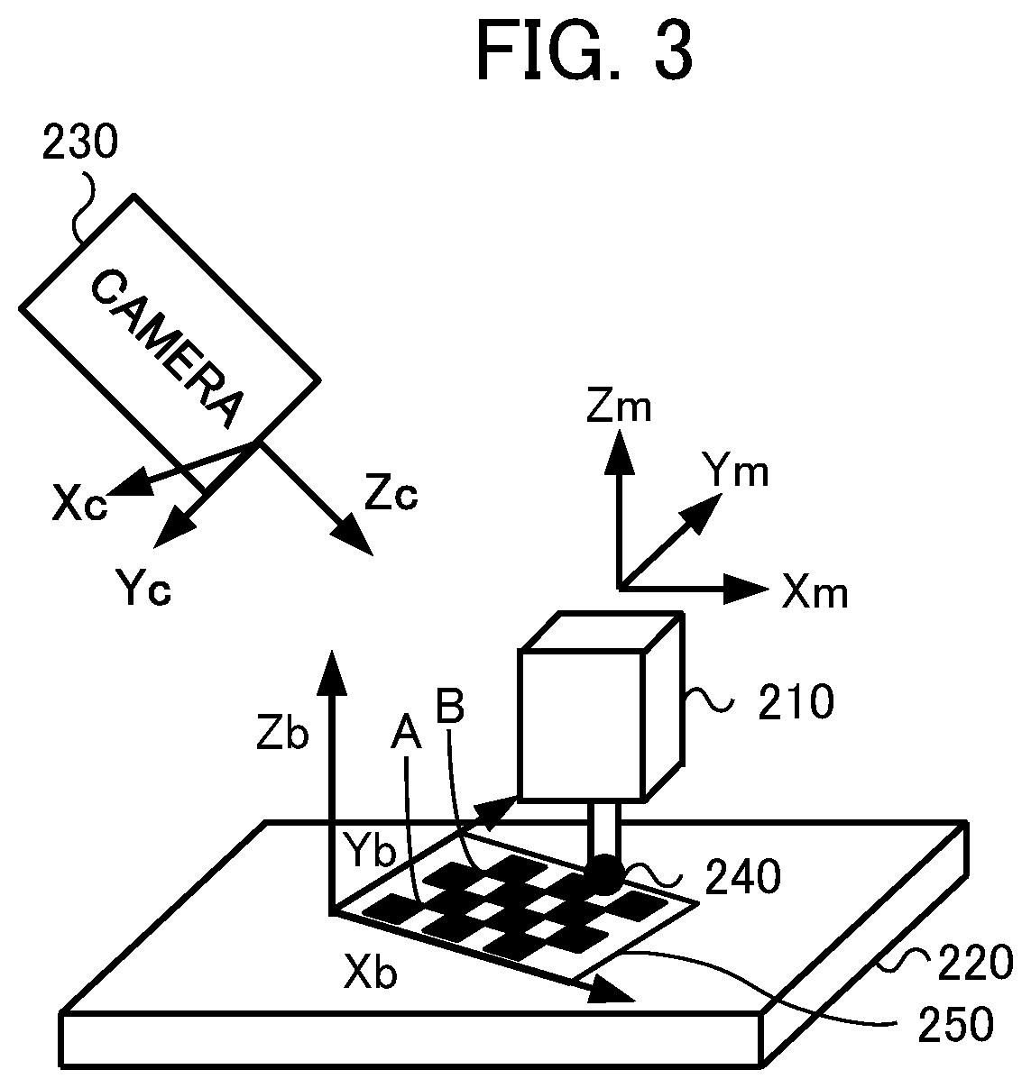
[0167]A third embodiment will then be described. The third embodiment differs from the first embodiment in that the camera calibration device uses a 3D camera as the camera included in the machine tool. In this way, in the third embodiment, since the camera calibration device can directly acquire the position of the tip end of the touch probe 240 seen from the camera coordinate system Σc, when the machine coordinates of the tip end of the touch probe 240 are known, the operation of touching the checkerboard 250 is not needed. Hence, in the following description, instead of the touch point, the position of the tip end of the touch probe 240 is also referred to as the “tip end position”.

[0168]Hence, in the third stage of the third embodiment, the machine coordinates (Xtm, Ytm, Ztm) of the tip end position in the machine coordinate system Σm and the coordinates (Xtc, Ytc, Ztc) in the camera coordinate system Σc are associated with each other as indicated in formula (12). Hence, the cam...


PUM


Abstract

To provide a camera calibration device and a camera calibration method which can easily calibrate a relationship between a machine coordinate system of a machine tool and a camera coordinate system of a camera. A camera calibration device calibrates an imaging means of a machine tool, the machine tool includes: a touch probe which acquires one point whose machine coordinates are known; a camera which images the one point and a pattern including a feature used for calibration; and a drive mechanism which moves a table or a spindle in two orthogonal directions and an image obtained by imaging the one point and the pattern and images obtained by imaging the pattern or / and the one point when the table or a machining machine is moved in the two directions are used to calculate an external parameter by calculating a positional posture relationship between the machine coordinate system and the pattern.

Description

[0001]This application is based on and claims the benefit of priority from Japanese Patent Application No. 2018-213798, filed on 14 Nov. 2018, the content of which is incorporated herein by reference.BACKGROUND OF THE INVENTIONField of the Invention[0002]The present invention relates to a camera calibration device and a camera calibration method which calibrate a relationship between a machine coordinate system set on a machine tool and a camera coordinate system of a camera installed in the machine tool.Related Art[0003]Conventionally, as a method of calibrating a relationship between a machine coordinate system set on a machine tool and an image coordinate system of a camera installed in the machine tool, a method is known which uses a calibration instrument of a checkerboard, a dot pattern or the like. For example, in the method described above, the calibration instrument is installed in a certain predetermined place which is stationary with respect to the camera and whose machin...

Claims


Application Information

Patent Timeline
Patent Type & Authority Patents(United States)
IPC IPC(8): G06T7/80B23Q17/22G01B11/03
CPCG06T7/80B23Q17/2233G01B11/03G06T2207/30108H04N23/64H04N23/695G06T2207/30208G01B21/042G01B5/004
Inventor SUGITA, YUUKI
Owner FANUC LTD
Why Eureka
Try Eureka