Measurement apparatus, test method, and physical property evaluation program for indentation creep test, and recording medium recording physical property evaluation program

a technology of indentation creep and measurement apparatus, which is applied in the direction of measuring devices, investigating material hardness, instruments, etc., can solve the problems of inability to determine the in-situ the indentation creep testing apparatus in the related art cannot determine the quantity of time change (t) of indentation surface deformation, etc., to achieve the effect of easy induction of a relationship

Active Publication Date: 2020-05-26
NAT INST OF ADVANCED IND SCI & TECH
View PDF10 Cites 0 Cited by
  • Summary
  • Abstract
  • Description
  • Claims
  • Application Information

AI Technical Summary

Benefits of technology

[0081]A method of analysis using a measurement apparatus, a test method, and a physical property evaluation program of the present invention is based on a constant load value P0 and a value of a contact area A directly measured in the middle of an indentation creep test. Therefore, it is possible to easily induce a relationship between stress and strain rate of viscoelasticity only from which an influence of plasticity generated during the test is removed, and it is possible to evaluate a creep index n and a creep constant k, which are creep physical property values, simultaneously, easily, and quickly.

Problems solved by technology

Such a situation brings about various problems in a size-conscious industrial product.
Furthermore, one test requires several hours at minimum to several months at a maximum so that an immense amount of time and effort is required to complete the whole tests.
However, a typical indentation creep testing apparatus in the related art cannot determine an in-situ quantity of a time change γ(t) of deformation of an indentation surface on a test piece during load application.

Method used


Image

  • Measurement apparatus, test method, and physical property evaluation program for indentation creep test, and recording medium recording physical property evaluation program
  • Measurement apparatus, test method, and physical property evaluation program for indentation creep test, and recording medium recording physical property evaluation program
  • Measurement apparatus, test method, and physical property evaluation program for indentation creep test, and recording medium recording physical property evaluation program

Examples


example 1

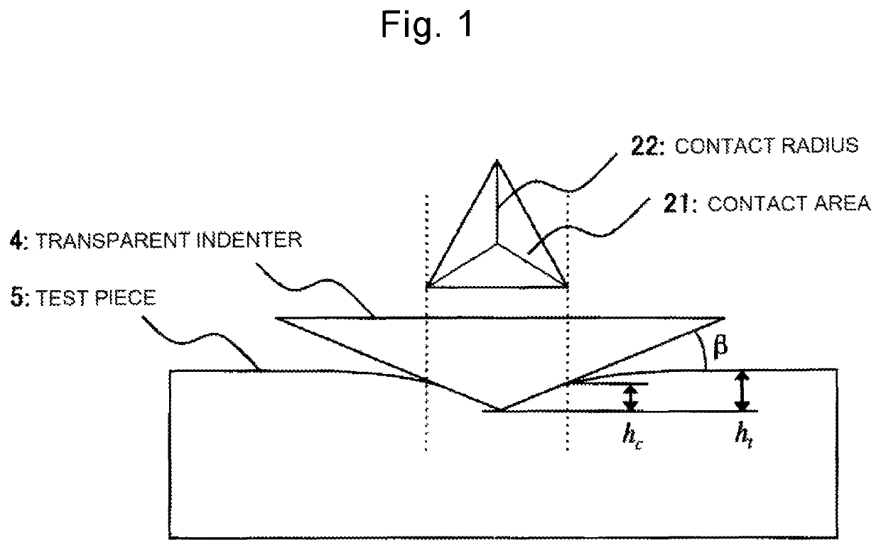
[0118]FIG. 5 illustrates actual measured values of an applied load (an indentation load) P0 and a contact area Ac during an indentation creep test carried out by the measurement apparatus according to the embodiment of the present invention in a case where a commercially available plastic plate (polycarbonate (PC)) is used as a specimen. The indentation creep test was carried out with respect to a plate-like test piece (10×10×5 mm) at room temperature (T=21.0° C.), using a diamond Berkovich indenter having a three-sided pyramidal tip and an inclined face angle β of 24.7 degrees. FIG. 5 illustrates a case where a constant applied load (P0=20.000 gf=196.14 mN) is loaded for a predetermined testing time (t=300 seconds), representing a creep curve in which the contact area Ac increases over time. In the following analysis of the power-law creep, viscoelastic analysis was practiced in regard to test data from which data for 10 seconds just after the start of loading was removed. The time...

example 2

[0130]FIG. 11 illustrates actual measured values of an applied load (an indentation load) P0 and a contact area Ac during an indentation creep test carries out by the measurement apparatus according to the embodiment of the present invention in a case where a commercially available synthetic-resin plate (polymethyl methacrylate (PMMA)) is used as a specimen. The indentation creep test was carried out with respect to a plate-like test piece (5×8×1 mm) at room temperature (T=24.0° C.), using a diamond Berkovich indenter having a three-sided pyramidal tip and an inclined face angle β of 25.0 degrees. FIG. 11 illustrates a case where a constant applied load (Po=1.000 gf=9.807 mN) is loaded for a predetermined testing time (t=300 seconds), representing a creep curve in which the contact area Ac increases over time.

[0131]FIG. 12 is a graph plotting natural logarithms of the contact stress as the X-axis, and plotting natural logarithms of a viscoelastic strain rate as the Y-axis in accorda...

example 3

[0138]FIG. 13 illustrates actual measured values of an applied load (an indentation load) P0 and a contact area Ac during an indentation creep test according to the embodiment of the present invention in a case where a commercially available magnesium alloy (AZ31) is used as a specimen. The indentation creep test was carried out with respect to a plate-like test piece (10×10×1.6 mm) at room temperature (T=25.0° C.), using a diamond Berkovich indenter having a three-sided pyramidal tip and an inclined face angle β of 25.0 degrees. FIG. 13 illustrates a case where a constant applied load (P0=5.000 gf=49.035 mN) is loaded for a predetermined testing time (t=3000 seconds), representing a creep curve in which the contact area Ac increases over time.

[0139]FIG. 14 is a graph plotting natural logarithms of viscoelastic contact stress as the X-axis, and plotting natural logarithms of the viscoelastic strain rate as the Y-axis in accordance with Formula 13, where the base is represented by e....


PUM

PropertyMeasurementUnit
Young's modulus E'aaaaaaaaaa
Young's modulusaaaaaaaaaa

Abstract

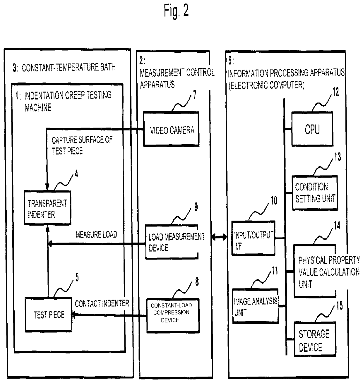
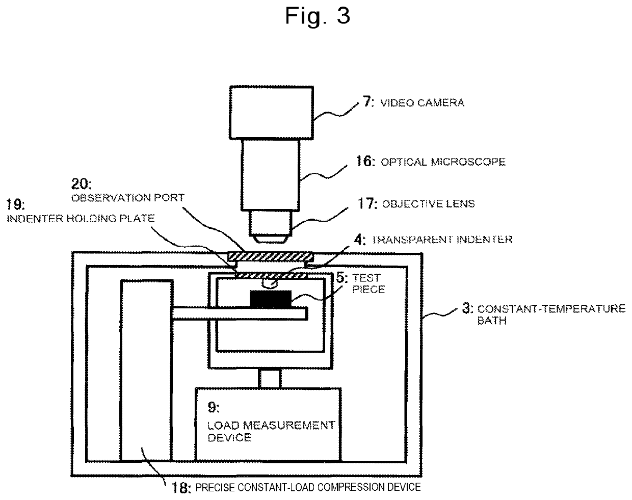
A measurement apparatus for carrying out an indentation creep test on a specimen, including a measurement control apparatus that includes a load measurement device, a constant-load compression device configured to compress a tip of a transparent indenter to a surface of the specimen, and an image capturing device configured to optically capture an image including a contact area portion which is a part of the specimen to which the load is applied by the constant-load compression device. The apparatus also includes an information processing apparatus that includes an image analysis unit configured to analyze a contact area, and a physical property value calculation unit. The physical property value calculation unit conducts linear regression with respect to a plot of a logarithmic value of the contact stress and a logarithmic value of the contact strain rate so as to determine a creep index n and creep constant k.

Description

TECHNICAL FIELD[0001]The present invention relates to a measurement apparatus, a test method, and a physical property evaluation program to evaluate creep physical property values based on results of an indentation creep test, and relates to a recording medium recording the physical property evaluation program.BACKGROUND ART[0002]In the related art, it is known that a phenomenon called “creep” occurs in materials such as metals, polymers, and ceramics and that an object applied with a continuous load for long periods of time changes its size over time. Such a situation brings about various problems in a size-conscious industrial product. To prevent such problems, it is important to formulate and understand creep characteristics for each material at the time of designing the industrial product.[0003]To describe a creep phenomenon with a formula, the following means is popularly practiced: that is, to use a definite relationship between increment of strain c and stress per unit time t...

Claims


Application Information

Patent Timeline
Patent Type & Authority Patents(United States)
IPC IPC(8): G01N3/42G01N3/54
CPCG01N3/54G01N3/42G01N2203/0078G01N2203/0071G01N2203/0286G01N2203/0094G01N2203/0218G01N2203/0075
Inventor MIYAJIMA, TATSUYA
Owner NAT INST OF ADVANCED IND SCI & TECH
Why Eureka
Try Eureka