Area abnormality detecting system and area abnormality detecting method

a detecting system and area technology, applied in the field of detecting systems and detecting methods, to achieve the effect of easy rebuilding the relationship

Active Publication Date: 2019-04-02
DELTA ELECTRONICS INC
View PDF12 Cites 0 Cited by
  • Summary
  • Abstract
  • Description
  • Claims
  • Application Information

AI Technical Summary

Benefits of technology

[0006]The main object of the present invention is to provide an area abnormality detecting system and an area abnormality detecting method, which constitute multiple areas of a space respectively by grouping a plurality of blocks having the same size, so as to easily define size, amount and position of each area of the space, and define serving areas of the space that multiple apparatuses and sensors take charge of.
[0010]The present invention firstly segments the space into a plurality of blocks with same size, and defines the areas of the space by the plurality of blocks, and then relates the sensors and the apparatuses with each area which needs to be served. Therefore, when each of the areas of the space has greatly changed (redecoration for example), the system can re-define each area with the plurality of blocks quickly, and easily rebuild the relationship among the sensors, the apparatuses and the re-defined areas of the space.

Problems solved by technology

However, if the indoor spaces of the building have a great change (for example, the building is redecorated), the manager needs to reset corresponding parameters of the algorithm of the system according to the variation of the indoor spaces in order to rebuild the relationship among each of the indoor apparatuses, each of the sensors and each of the changed areas, which is very complicated.

Method used


Image

  • Area abnormality detecting system and area abnormality detecting method
  • Area abnormality detecting system and area abnormality detecting method
  • Area abnormality detecting system and area abnormality detecting method

Examples


first embodiment

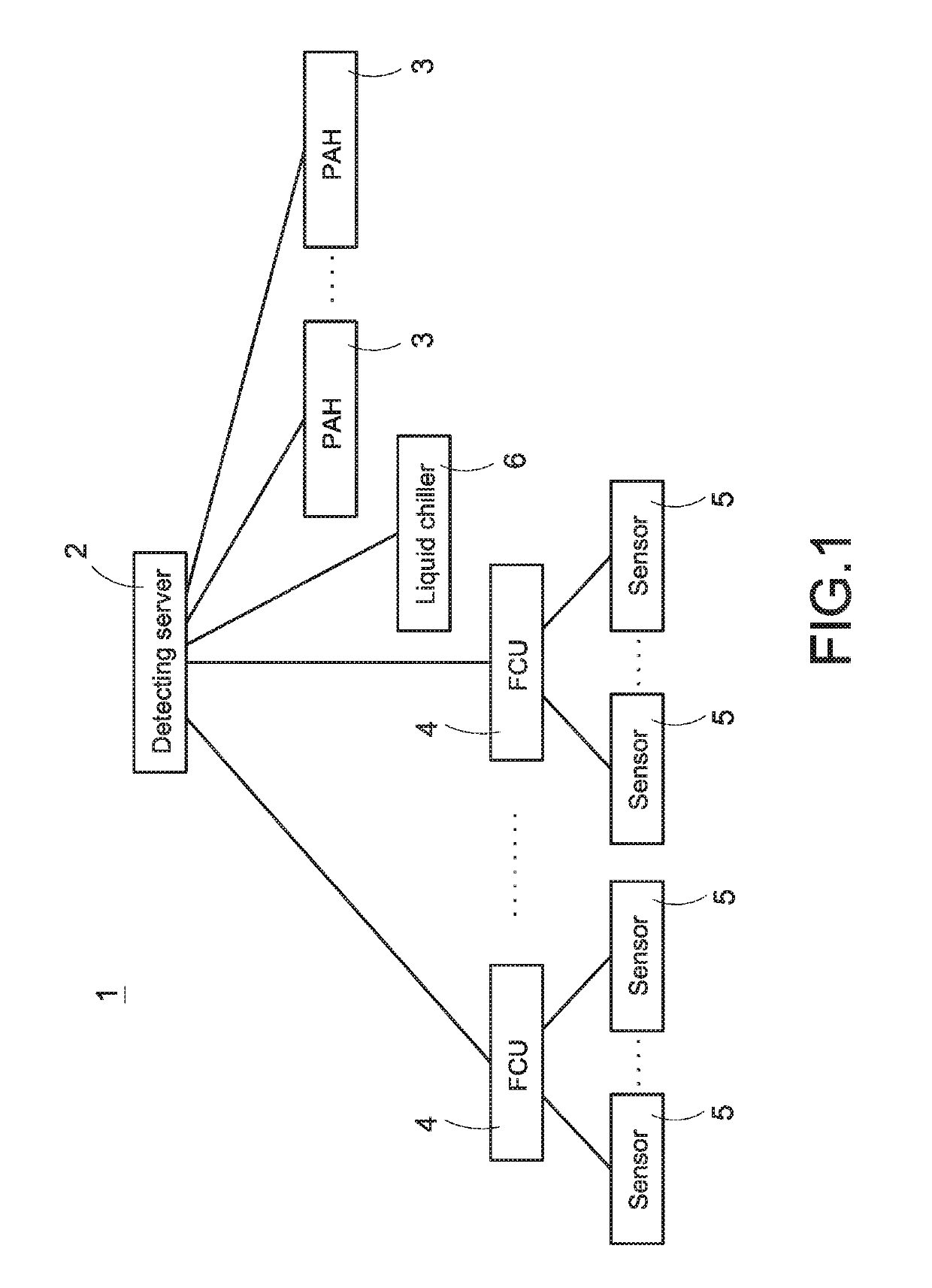
[0025]FIG. 1 is a schematic view showing system arrangement of a first embodiment according to the present invention. The present invention discloses an area abnormality detecting system 1 (refers to as the system 1 hereinafter), as shown in FIG. 1, and the system 1 includes a detecting server 2, a plurality of sensors 5 and a plurality of apparatuses. In this invention, the plurality of apparatuses can be any type of apparatus, such as pre-cooling air handling unit (PAH) 3, fan coil unit (FCU) 4, liquid chiller 6, etc., of an intelligent air-conditioning system, but not limited thereto.

[0026]The detecting server 2 can directly connect with each apparatus, or alternatively connect to each PAH 3 and the liquid chiller 6 through a programmable logic controller (PLC, not shown in FIG. 1), and connect to each FCU 4 through zone controller(s) (ZC(s), not shown in FIG. 1) arranged in each area. The plurality of sensors 5 in this embodiment are arranged in each area respectively, which are...


PUM


Abstract

An area abnormality detecting system includes multiple apparatuses, multiple sensors and a detecting server. The system is adopted in a space, which is segmented into several blocks with same size. Multiple areas of the space are defined by the blocks separately. The apparatuses are respectively corresponding to each area for providing environmental improving services. The sensors are respectively corresponding to each area for sensing indoor environment of each area. After an abnormality occurs, the detecting server determines an abnormal area and an occurring time corresponding to the abnormality, and obtains apparatus parameters of apparatuses corresponding to the abnormal area that are recorded at the occurring time, so as to determine the occurring reason for the abnormality based on the apparatus parameters.

Description

BACKGROUND OF THE INVENTION1. Field of the Invention[0001]The invention relates to a detecting system and a detecting method, and in particularly to an area abnormality detecting system and an area abnormality detecting method.2. Description of Prior Art[0002]In order to adjust comfort degree of indoor space temperature, the modern buildings now are usually arranged with central air-conditioning systems, and use indoor apparatuses, such as pre-cooling air handling units (PAHs), fan coil units (FCUs), etc., to blow cold air into the buildings. Also, the buildings use a lot of sensors to detect various environmental statuses inside the buildings.[0003]General speaking, these indoor apparatuses and sensors are usually corresponding to different areas inside the building, such as lobby, meeting rooms, working areas, spare rooms, etc. The sensors are used to detect various environmental statuses, such as temperature, humidity and person existence in each area, and each of the indoor appa...

Claims


Application Information

Patent Timeline
Patent Type & Authority Patents(United States)
IPC IPC(8): G05B21/00G05B15/00G05B13/00G01M1/38G05D23/00G05B15/02F24F11/30F24F11/32F24F110/10F24F110/20F24F110/50F24F110/70F24F120/10
CPCF24F11/30G05B15/02F24F11/32F24F2120/10F24F2110/20F24F2110/50F24F2110/70F24F2110/10F24F11/77F24F11/64F24F11/84
Inventor CHEN, MENG-SENGLO, TIEN-SZULEE, HSIANG-PIN
Owner DELTA ELECTRONICS INC
Why Eureka
Try Eureka