Pneumatic solar tracking system for solar panels

a solar panel and tracking system technology, applied in pneumatic programme control, program control, instruments, etc., can solve the problems of complex machines subject to numerous problems, physical driven movement of solar panels is typically performed in only a limited number, etc., and achieve the effect of maximizing the exposure of the upper surfa

Active Publication Date: 2022-08-02
UNITED ARAB EMIRATES UNIVERSITY +1
View PDF14 Cites 0 Cited by
  • Summary
  • Abstract
  • Description
  • Claims
  • Application Information

AI Technical Summary

Benefits of technology

[0004]An optical sensor is provided for detecting the angular position of the sun. A controller is in communication with the optical sensor, and is configured to selectively and individually actuate each of the plurality of pneumatic actuators to adjust the angular orientation of the solar panel to maximize exposure of the upper surface of the solar panel to incident solar radiation from the sun.

Problems solved by technology

Although a wide variety of solar tracking systems exist, the physical driven movement of the solar panel is typically performed in only a limited number of ways, most often involving relatively complex mechanical arrangements of gears, rods, wheels, pulleys or chains, etc.
Unfortunately, these complex machines are subject to numerous problems, particularly since a flaw in, or misalignment of, only one part tends to affect any other connected parts.

Method used


Image

  • Pneumatic solar tracking system for solar panels
  • Pneumatic solar tracking system for solar panels
  • Pneumatic solar tracking system for solar panels

Examples


Embodiment Construction

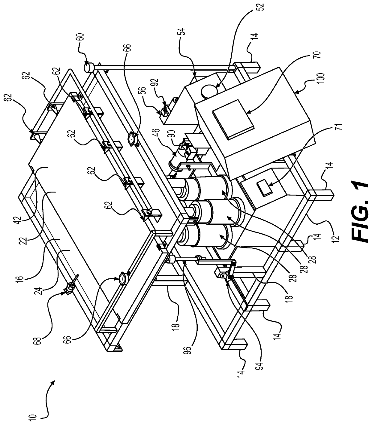
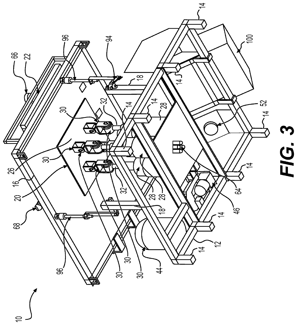
[0014]Referring now to FIGS. 1-3, there is shown a pneumatic solar tracking system for solar panels 10, which adjusts the angular orientation of a solar panel 22 to maximize exposure of an upper surface 42 thereof to incident solar radiation from the sun as the sun moves across the sky. The pneumatic solar tracking system 10 includes a base 12 and a platform 16 supported above the base 12. It should be understood that the overall dimension and configuration of the base 12 (including legs 14) are shown in FIGS. 1-3 for exemplary purposes only. Similarly, it should be understood that the overall dimension and configuration of the platform 16 are also shown in FIGS. 1-3 for exemplary purposes only. Additionally, it should be understood that the solar panel 22 is shown for exemplary purposes only, and that the pneumatic solar tracking system 10 may be used with any suitable type of solar panel, solar cell, solar module, solar concentrator or the like.

[0015]As best seen in FIG. 3, the pl...


PUM

PropertyMeasurementUnit
axis of rotationaaaaaaaaaa
rotationaaaaaaaaaa
pressureaaaaaaaaaa

Abstract

The pneumatic solar tracking system for solar panels adjusts the angular orientation of a solar panel to maximize exposure of an upper surface of the solar panel to incident solar radiation from the sun as the sun moves across the sky. The pneumatic solar tracking system includes a base and a platform supported above the base. The platform has an opening formed therein. A plurality of pneumatic actuators are supported on the base beneath the opening formed in the platform. The solar panel is supported on an upper surface of the platform, and a plurality of pivotal connectors pivotally connect the lower surface of the solar panel to respective pistons of the plurality of pneumatic actuators. Each of the pivotal connectors pivots along at least two orthogonal axes. An optical sensor is provided for detecting and tracking the angular position of the sun.

Description

BACKGROUND1. Field[0001]The disclosure of the present patent application relates to solar power, and particularly to a pneumatic solar tracking system for solar panels that uses pneumatic actuators to adjust the orientation of the solar panel.2. Description of the Related Art[0002]Due to environmental concerns, solar power is of great interest. Although solar panels are typically mounted in areas where sunlight is expected to be abundant, as a result of the orbit and rotation of the Earth, the direction and alignment of solar panels with respect to the sun varies over time, both over the course of a single day, and also over the course of the year. Thus, in order to maintain proper orientation of the solar panel with respect to the position of the sun, the solar panel must be angularly displaced in order to track the apparent movement of the sun. Ideally, in order to maximize the sunlight striking the surface of the solar panel, the solar panel should be adjusted such that the sun's...

Claims


Application Information

Patent Timeline
Patent Type & Authority Patents(United States)
IPC IPC(8): H02S20/32F15B15/20G05B19/44G01K1/14G01K1/024G01B11/26G01C9/02
CPCH02S20/32F15B15/20G01B11/26G01C9/02G01K1/024G01K1/14G05B19/44G05B2219/25312H02S50/00F15B15/02F15B2211/7107F15B2211/765F15B15/1404F15B2211/6303F15B2211/8855F24S30/48F24S2030/115F24S2030/12F24S50/20G05B2219/39462
Inventor SHAREEF, HUSSAINSHADID, TARIK TAYSEER
Owner UNITED ARAB EMIRATES UNIVERSITY
Why Eureka
Try Eureka