
Illumination system with a light guide and an emission element

a technology of light guide and emission element, which is applied in the field of illumination system, can solve the problems of evlt treatment requiring significantly higher laser power, and affecting the effect of ejection

Active Publication Date: 2022-08-09
SCHOTT AG
View PDF26 Cites 0 Cited by
  • Summary
  • Abstract
  • Description
  • Claims
  • Application Information

AI Technical Summary

Benefits of technology

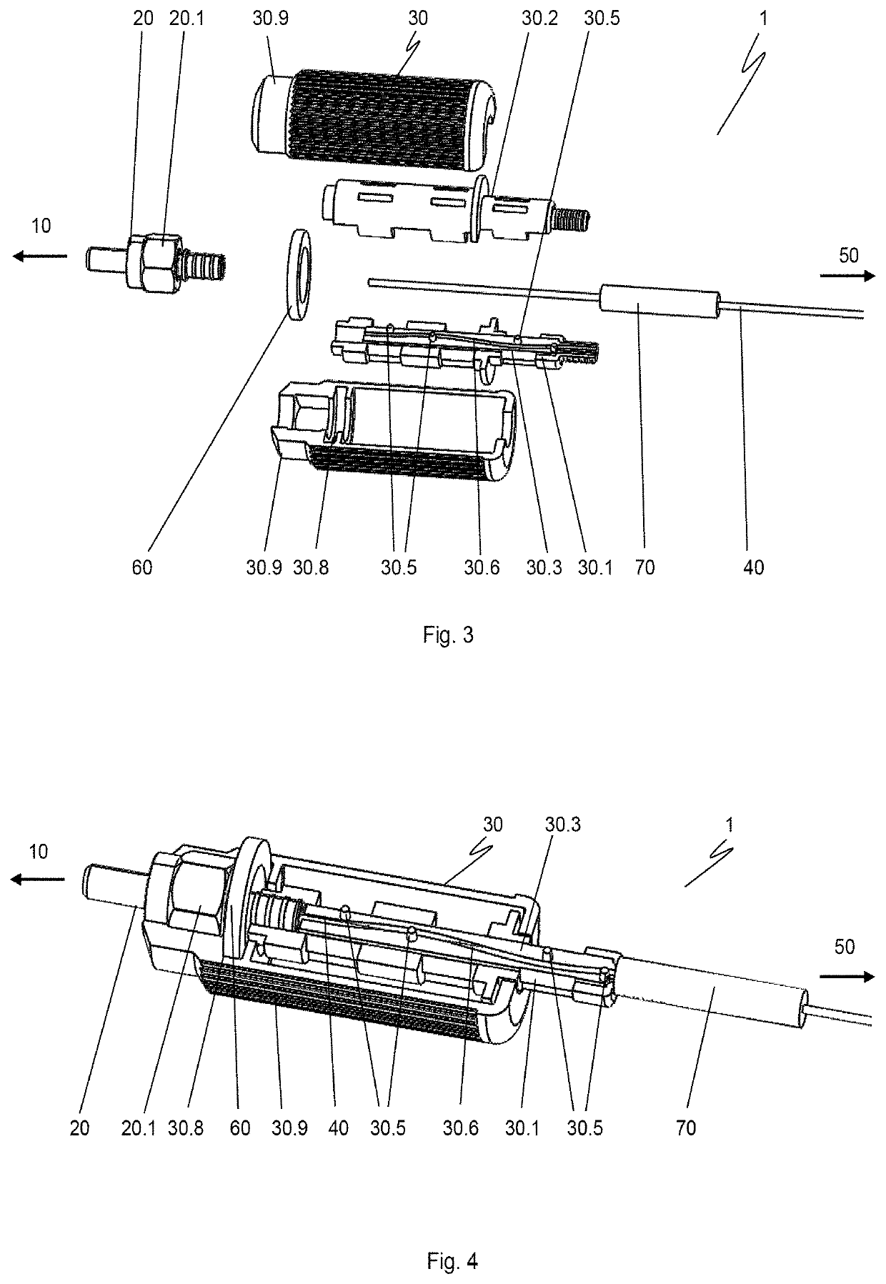
[0024]The object of the invention is achieved by virtue of the fact that the connector housing has devices for reducing an influence of a range of variation of the numerical aperture NAL of the laser light source of the laser light from the laser light source coupled into the connector, in such a way that the emission behaviour of the emission element is substantially independent of the range of variation of the numerical aperture NAL. This facilitates a very cost-effective way of reducing the influence of an NAL variation or a change on the emission characteristic of, e.g., such components (emission elements), as described at the outset, to the effect that a range of variation of the input coupling NA of the laser light source NAL or of an input coupling fibre exerts virtually no more influence on, e.g., the homogeneity of the emission or else its efficiency. Particularly in the case of cylindrical diffusers, where it comes down to an intensity profile over the diffuser length that is as uniform as possible, this inventive measure can significantly stabilize the latter in respect of possible NA variations during input coupling. If the various NA values in the system of laser, light guide and diffuser are not matched to one another, it is not possible to achieve demanded, specified emission characteristics and / or emission intensities, or the spatial distribution thereof, of a diffuser. Particularly in the case where the NAL of the radiation of the employed laser changes, be it on account of changes of a laser per se, for example due to ageing, misalignment, the influence of temperature, etc., or on account of an exchange, replacement or use of an alternative laser, this influence on the emission characteristic or efficiency of an emission element can be significantly reduced by the approach according to the invention, virtually without any additional outlay. Here, the assumption can further be made that, as a rule, the NA values of the light guide (supply fibre) and of the diffuser (emission element) remain substantially constant or are substantially constant and these are designed to match one another. The latter holds true particularly in view of the fact that, in the case of cost-sensitive applications, it cannot be justifiable and by no means be practical to offer or keep available very different combinations of supply fibres and diffusers in order to react to the ageing of a laser, for example, or to compensate product variations in the case of the same laser modules per se. Accordingly, the connector housing comprises at least an apparatus, or is an apparatus, to at least reduce the influence of a changing or changeable numerical aperture of a laser on the emission, for example within the meaning of the emission intensity and emission homogeneity of an emission element.
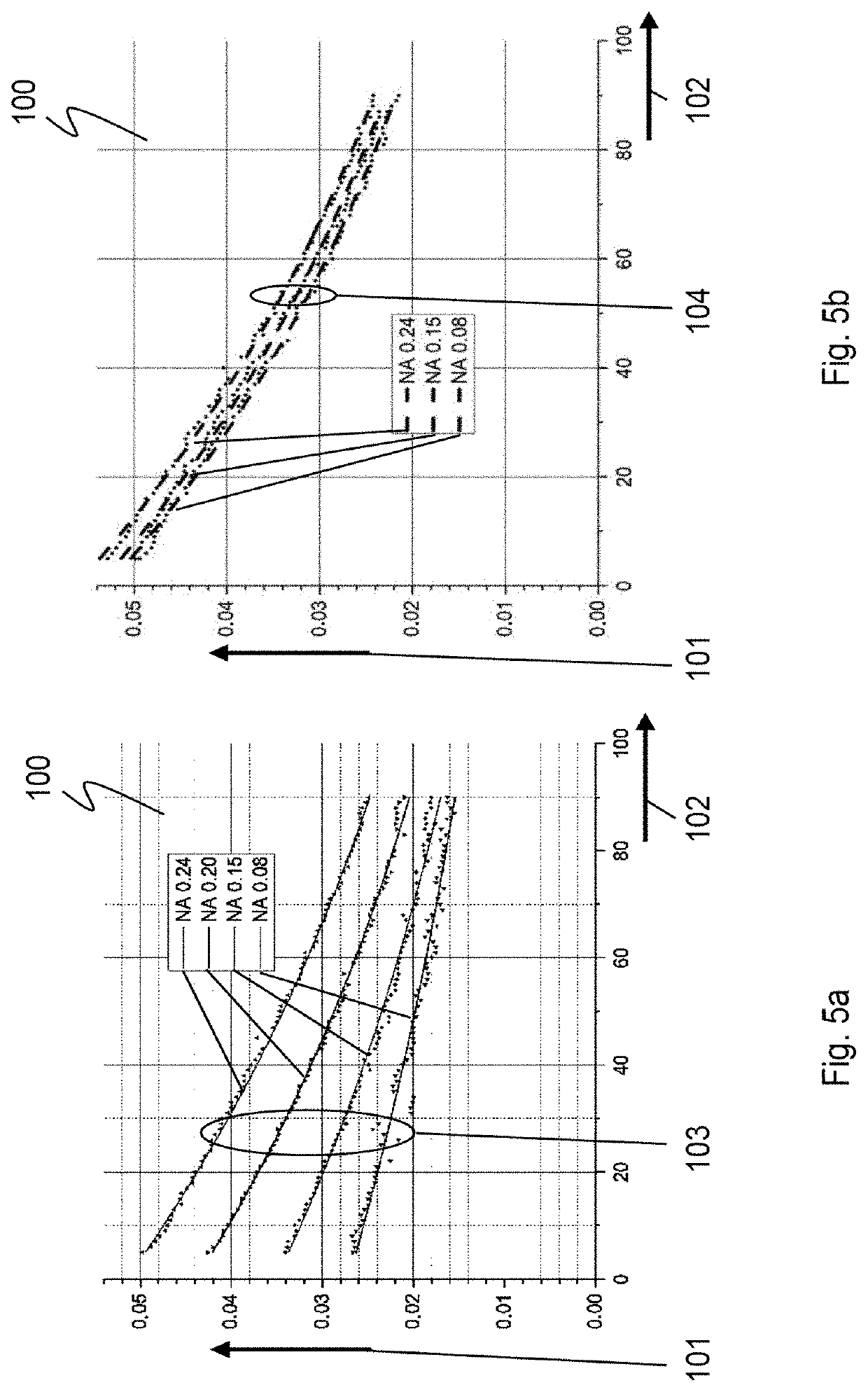
[0047]What can be achieved in a preferred embodiment variant is that the emission behaviour of the emission element, embodied as a cylindrical diffuser, varies in the case of a range of variation ranging from at least 0.08 to 0.24, preferably also ranging from 0.05 to 0.30, of the numerical aperture NAL of the laser light source of the laser light from the laser light source coupled into the connector, in such a way that the emission intensity, measured as relative luminance, at the diffuser surface drops no more than 40%, particularly preferably by no more than 20%, over its length in relation to its maximum value of the relative luminance. In particular, this can minimize or completely solve the problems mentioned the outset.

Problems solved by technology

As a result of the targeted lateral emission of the laser power by means of the diffuser, the vessel inner wall is subsequently strongly heated, leading to the vein collapsing and becoming sealed.
Here, for uniform treatment, the light guide with the emission element is often manually pulled through the vein section to be treated at a rate that is as constant as possible; this complicates the application, since further cell damage may arise at a site in the case of non-compliance or excessive dwell time.
However, EVLT treatment requires significantly higher laser powers.
However, these are comparatively expensive to produce as they require specific preforms.
However, no specific approaches as to how this can be realized in cost-effective and practical fashion for the applications set forth at the outset are disclosed.
A disadvantage here is that, depending on the ambient temperature or the temperature of use, the mechanical pressure on the fibre generated thus is not defined on account of a certain plastic deformation of the buffer material and may change over time and / or that uncontrolled, local loads or radii of curvature that are too small, which at least damage the fibre, set in.
Moreover, such an approach represents additional outlay in manufacturing.
However, no specific approaches are described therein as to how this can be implemented in respect of, firstly, a certain degree of robustness and, secondly, practicality.
If the various NA values in the system of laser, light guide and diffuser are not matched to one another, it is not possible to achieve demanded, specified emission characteristics and / or emission intensities, or the spatial distribution thereof, of a diffuser.
The latter holds true particularly in view of the fact that, in the case of cost-sensitive applications, it cannot be justifiable and by no means be practical to offer or keep available very different combinations of supply fibres and diffusers in order to react to the ageing of a laser, for example, or to compensate product variations in the case of the same laser modules per se.
Should the connecting means no longer be functional, it is no longer possible to establish a connection to the light source and / or ensure optimal light input coupling.
By contrast, if the light guide is destroyed or at least partly damaged, it is no longer possible to transport radiation to the site of the human body to be treated.
Quartz fibres with a hexagonal or any other polygonal-like or irregularly formed core cross-sectional structure additionally help to reduce the sensitivity to NA variations of the laser light source described at the outset, but are more expensive in production, as has already been mentioned.

Method used


Image

  • Illumination system with a light guide and an emission element
  • Illumination system with a light guide and an emission element
  • Illumination system with a light guide and an emission element

Examples


Embodiment Construction

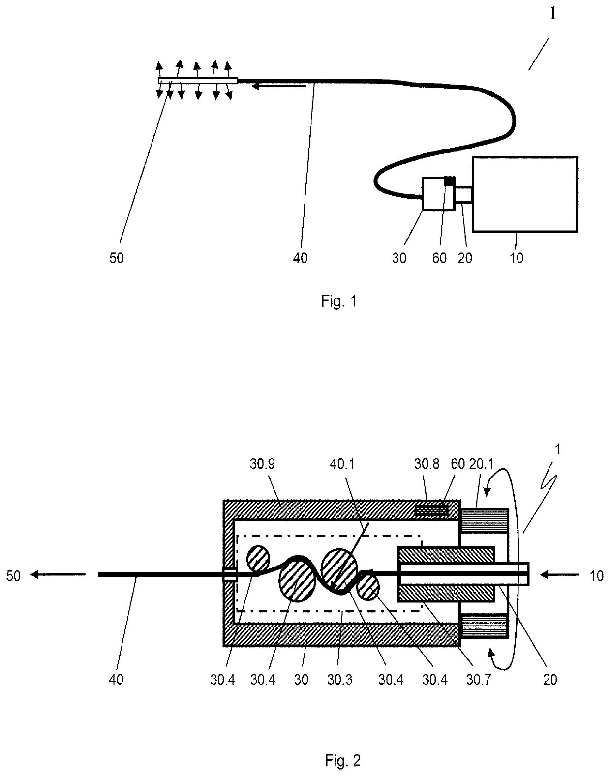
[0057]FIG. 1 schematically shows the setup of an illumination system 1 according to the invention. A medical PDT application is illustrated in exemplary fashion in this case.

[0058]In the shown example, the illumination system 1 consists of a laser light source 10, which emits light in a certain spectral range when in operation. For PDT or PIT applications, as described the outset, use is made of lasers which emit at a wavelength matched to a biochemically modified dye (photosensitizer) administered previously, usually in the visible range, for example in the green spectral range at 532 nm or in the red spectral range at 690 nm, for example. A light guide 40 is connected at its proximal end to the laser light source 10 using a connector 20. At the distal end, the light guide 40 has an emission element 50 which is embodied as a cylindrical diffuser. As a rule, multimodal quartz fibres are used as light guides 40, wherein the connectors 20 are embodied, as a rule, as coaxial plug-in co...


PUM

PropertyMeasurementUnit
angle of rotationaaaaaaaaaa
wavelengthaaaaaaaaaa

Abstract

An illumination system is provided that includes a laser light source, a light guide, a connector, and an emission element. The laser light source has a numerical aperture. The light guide has a proximal end and a distal end. The connector has a connector housing and connects and / or assigns the laser light source at the proximal end. The emission element is at the distal end. The connector housing has a device that reduce an influence of a range of variation of the numerical aperture so that an emission behaviour of the emission element is independent of a range of variation of the numerical aperture.

Description

CROSS REFERENCE TO RELATED APPLICATIONS[0001]This application claims benefit under 35 USC § 119 of German Application No. 10 2019 123 448.4 filed Sep. 2, 2019, the entire contents of which are incorporated herein by reference.BACKGROUND1. Field of the Invention[0002]The invention relates to an illumination system comprising at least one laser light source with a numerical aperture NAL and a light guide which is connectable and / or assignable at a proximal end to the at least one laser light source by means of a connector with a connector housing and having an emission element at the distal end of the light guide.2. Description of Related Art[0003]Illumination systems find increasing use in medicine. Currently, it is possible to classify the following focuses of application: photodynamic therapy (PDT) or photoimmunotherapy (PIT) for tumour therapy, endovenous laser treatment (EVLT) for treating varicose veins, laser interstitial thermal therapy (LITT), and other applications, inter al...

Claims


Application Information

Patent Timeline
Patent Type & Authority Patents(United States)
IPC IPC(8): F21V7/04F21V33/00F21K9/61F21K9/65F21K9/69A61N5/06F21V21/32G02B6/42G02B6/26F21W131/20A61N5/067
CPCF21V33/0068A61N5/062F21K9/61F21K9/65F21K9/69F21V21/32G02B6/262G02B6/4204A61N5/067A61N2005/063F21W2131/20A61B18/22A61B2018/2205A61B2018/00404A61N2005/0602
Inventor SCHULTHEIS, BERNDKEIPER, OLIVERRUSSERT, HUBERTUSDIETRICH, ANDREAS
Owner SCHOTT AG
Learn More