Fuel pressure regulator

a technology of fuel pressure regulator and valve member, which is applied in the direction of functional valve types, machines/engines, electric control, etc., can solve the problems of affecting the operation of the fuel pressure regulator, the valve member may become stuck on the seat, and the current fuel pressure regulator may require added cost and complexity to ensure the desired operation. , the possibility of hysteresis is minimized, and the manufacturing time and expense is minimized

Active Publication Date: 2022-08-16
DELPHI TECH IP LTD
View PDF38 Cites 0 Cited by
  • Summary
  • Abstract
  • Description
  • Claims
  • Application Information

AI Technical Summary

Benefits of technology

[0005]Briefly described, a fuel pressure regulator includes a fuel inlet; a fuel outlet; a seating surface; and a valve member assembly. The valve member assembly includes a poppet and also includes a sealing member which is made of an elastomer material and which is annular in shape and including a sealing member surface. The sealing member is supported by the poppet. The valve member assembly is moveable between 1) a closed position in which the sealing member surface engages the seating surface, thereby preventing fuel flow from the fuel inlet to the fuel outlet and 2) an open position in which the sealing member surface is spaced apart from the seating surface, thereby allowing fuel flow from the fuel inlet to the fuel outlet. The fuel pressure regulator as disclosed herein allows for a positive seal in the closed position without the need for post processing of the seating surface such as coining, burnishing, and / or lapping of the seating surface because the sealing member is able to conform to the seating surface. By eliminating the need for post processing, manufacturing time and expenses can be minimized. Furthermore, the possibility of hysteresis is minimized since some axial misalignment between the seating surface and the sealing member does not affect sealing. Also furthermore, the sealing member is not susceptible to being stuck to the seating surface which provides ensured opening of the valve member assembly when desired.

Problems solved by technology

A known issue with such fuel pressure regulators is that movement of the valve member between open and closed positions is susceptible to hysteresis due to the possibility of misalignment occurring between the valve member and the seat.
Furthermore, if the valve member is made of an elastomer material, the valve member may become stuck on the seat because the valve member can elastically deform and wedge into the seat.
For these reasons, current fuel pressure regulators may require added cost and complexity to ensure desired operation.

Method used


Image

  • Fuel pressure regulator
  • Fuel pressure regulator
  • Fuel pressure regulator

Examples


Embodiment Construction

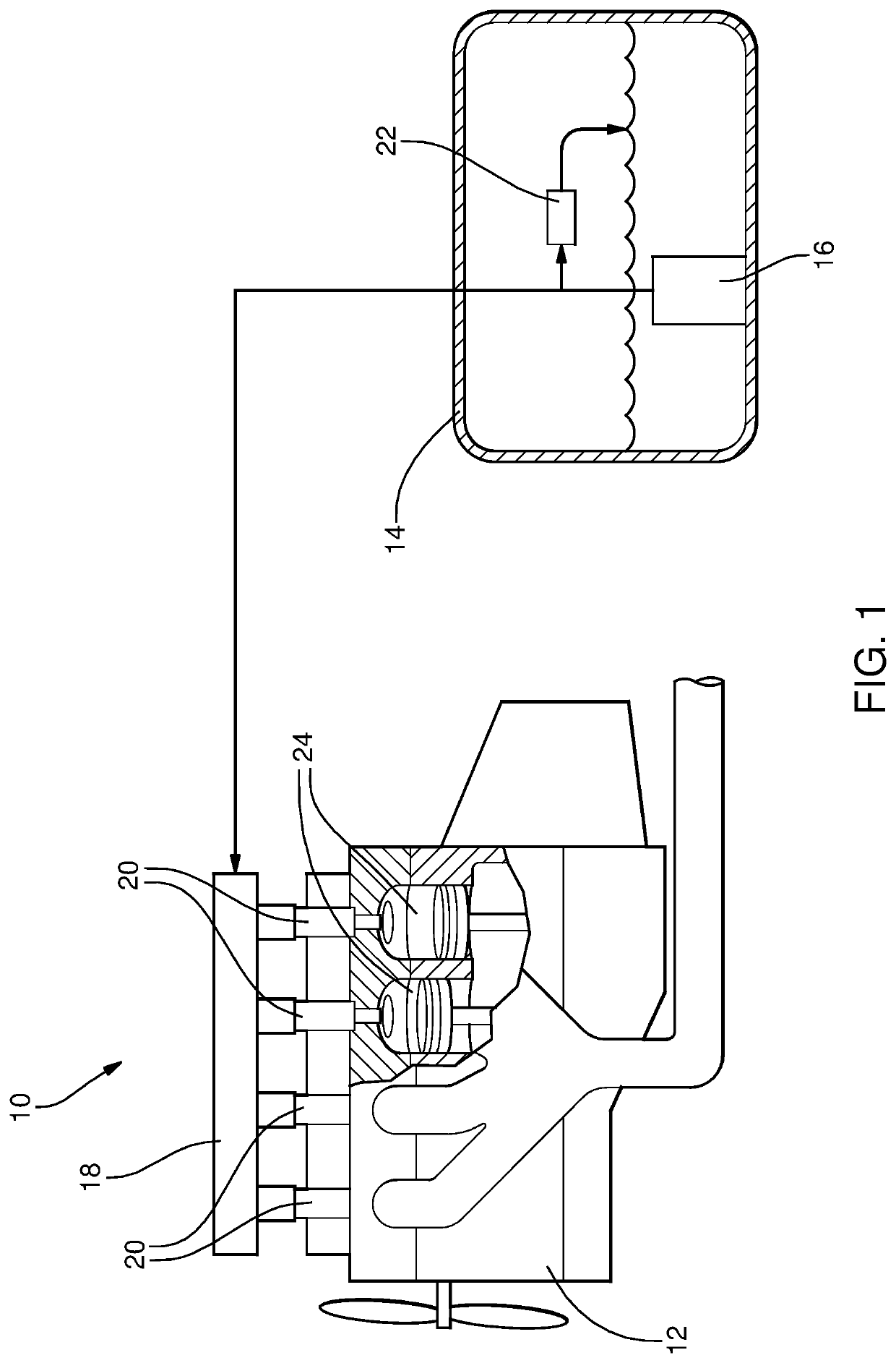
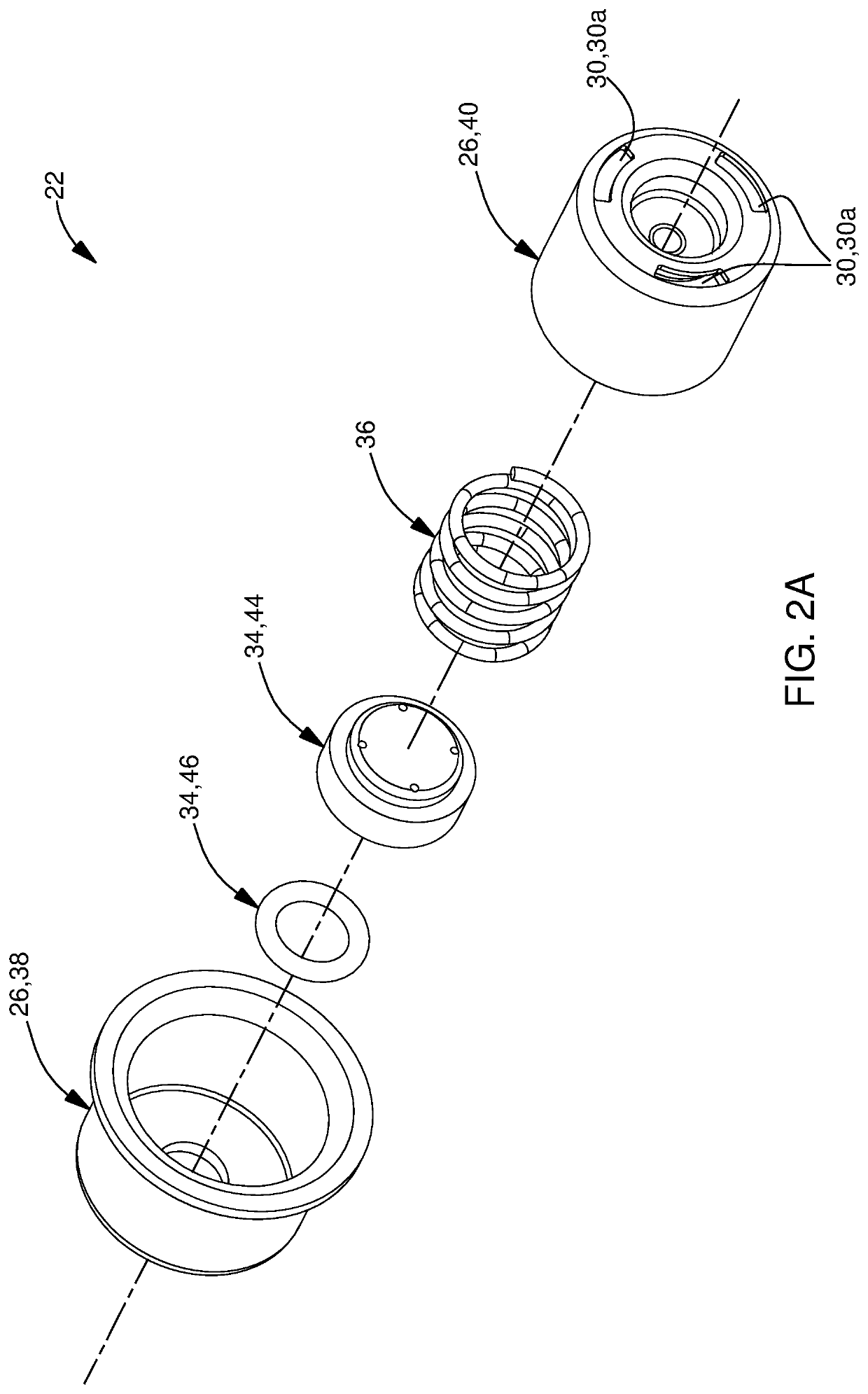
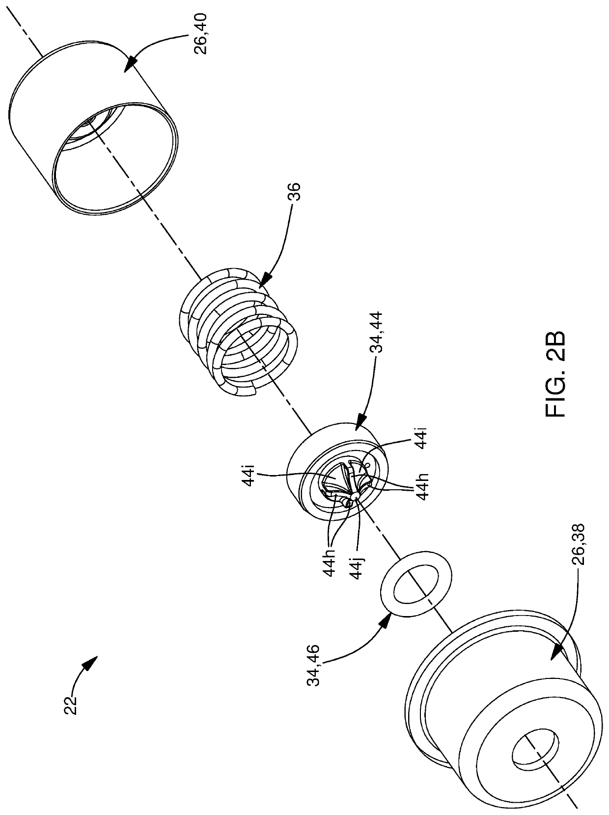
[0014]Referring initially to FIG. 1, a fuel system 10 is shown in simplified schematic form for supplying fuel to an internal combustion engine 12, by way of non-limiting example only, for a motor vehicle. Fuel system 10 includes a fuel tank 14 for storing a volume of fuel, a fuel pump 16 which may be located within fuel tank 14 as shown, a fuel rail 18 attached to internal combustion engine 12 and in fluid communication with fuel pump 16, a plurality of fuel injectors 20 in fluid communication with fuel rail 18, and a fuel pressure regulator 22 which regulates the fuel pressure within fuel rail 18. In operation, fuel pump 16 draws fuel from fuel tank 14 and pumps the fuel to fuel rail 18 under pressure. Each fuel injector 20 receives fuel from fuel rail 18 and injects the fuel to a respective combustion chamber 24 of internal combustion engine 12 for combustion of the fuel within combustion chambers 24. Fuel pressure regulator 22 maintains a substantially uniform pressure within fu...


PUM


Abstract

A fuel pressure regulator includes a fuel inlet; a fuel outlet; a seating surface; and a valve member assembly. The valve member assembly includes a poppet and also includes a sealing member which is made of an elastomer material and which is annular in shape and including a sealing member surface. The sealing member is supported by the poppet. The valve member assembly is moveable between 1) a closed position in which the sealing member surface engages the seating surface, thereby preventing fuel flow from the fuel inlet to the fuel outlet and 2) an open position in which the sealing member surface is spaced apart from the seating surface, thereby allowing fuel flow from the fuel inlet to the fuel outlet.

Description

TECHNICAL FIELD OF INVENTION[0001]The present invention relates to a fuel pressure regulator, and more particularly to a fuel pressure regulator which includes a seating surface and a sealing member which is made of an elastomer material and which is annular in shape such that the sealing member selectively engages the seating surface.BACKGROUND OF INVENTION[0002]Fuel systems for supplying liquid fuel, by way of non-limiting example only, gasoline or diesel fuel, to an internal combustion engine typically include a fuel tank for storing a volume of fuel, a fuel pump for pumping fuel from the fuel tank to a fuel rail mounted to the internal combustion engine. The fuel rail includes a plurality of fuel injectors such that each fuel injector is arranged to inject fuel, either directly or indirectly, to a respective combustion chamber of the internal combustion engine. The fuel rail provides a common volume of fuel from which each of the plurality of fuel injectors receives fuel. The fu...

Claims


Application Information

Patent Timeline
Patent Type & Authority Patents(United States)
IPC IPC(8): F02M55/04F02M63/00F16K17/04F02M63/02F02M69/54
CPCF02M55/04F02M63/0035F02M63/0052F02M63/0075F02M63/0235F02M69/54F16K17/0433F02M37/0029F02M37/0052F02D41/3836F02M2037/087F02D2250/31F02D2200/0602F02M63/005F02M63/0077F02M2200/9015
Inventor MORENO, ALEJANDRO
Owner DELPHI TECH IP LTD
Why Eureka
Try Eureka