
Pneumatic return for foot pedals associated with percussion instruments

a technology of foot pedals and percussion instruments, which is applied in the direction of instruments, musical instruments, percussion musical instruments, etc., can solve the problems of inability to implement, inconvenient operation, and inability to precisely locate the resting place of the piston on the diaphragm,

Active Publication Date: 2022-09-20
RUPRECHT DAVID S
View PDF3 Cites 2 Cited by
  • Summary
  • Abstract
  • Description
  • Claims
  • Application Information

AI Technical Summary

Benefits of technology

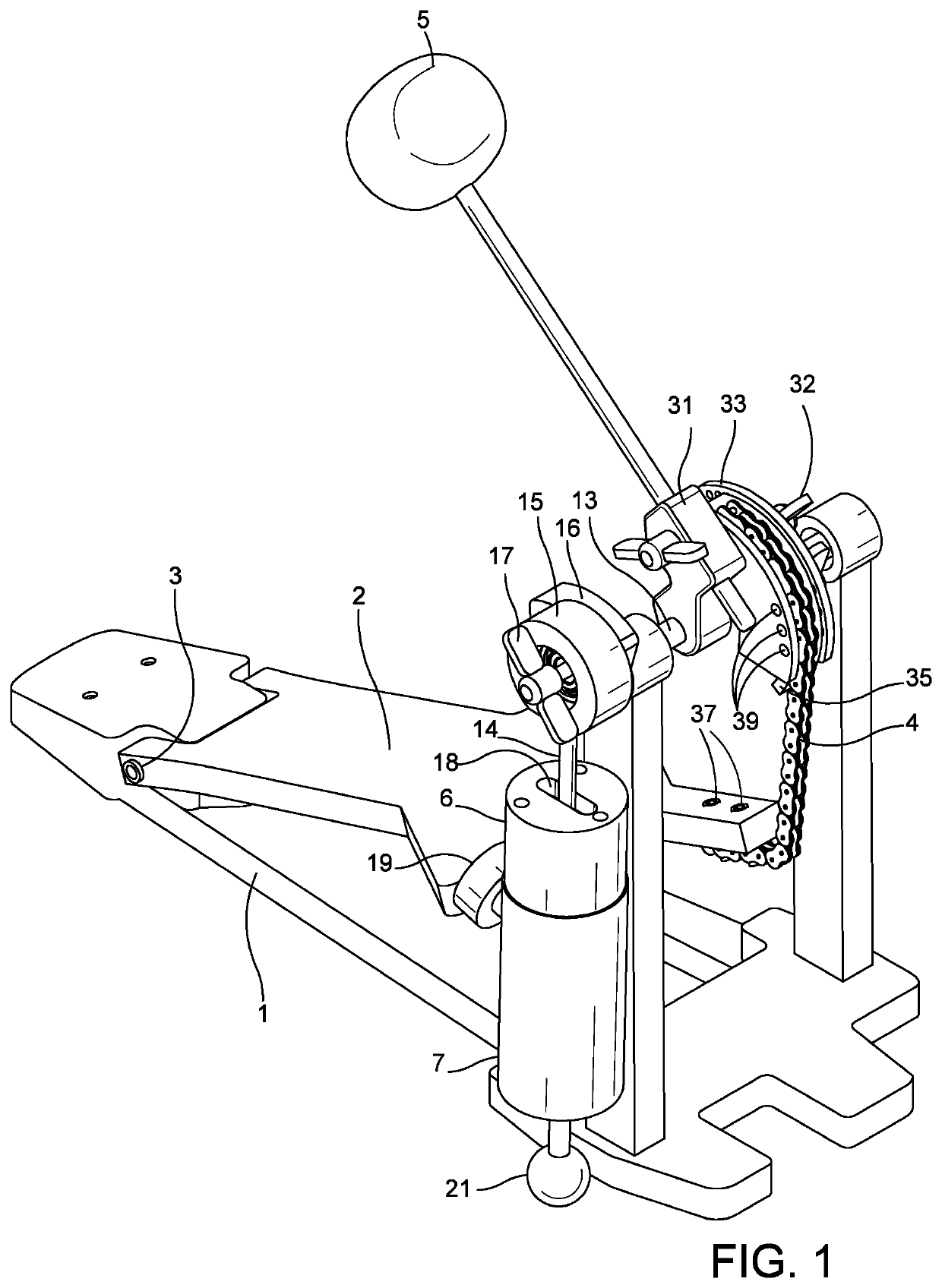
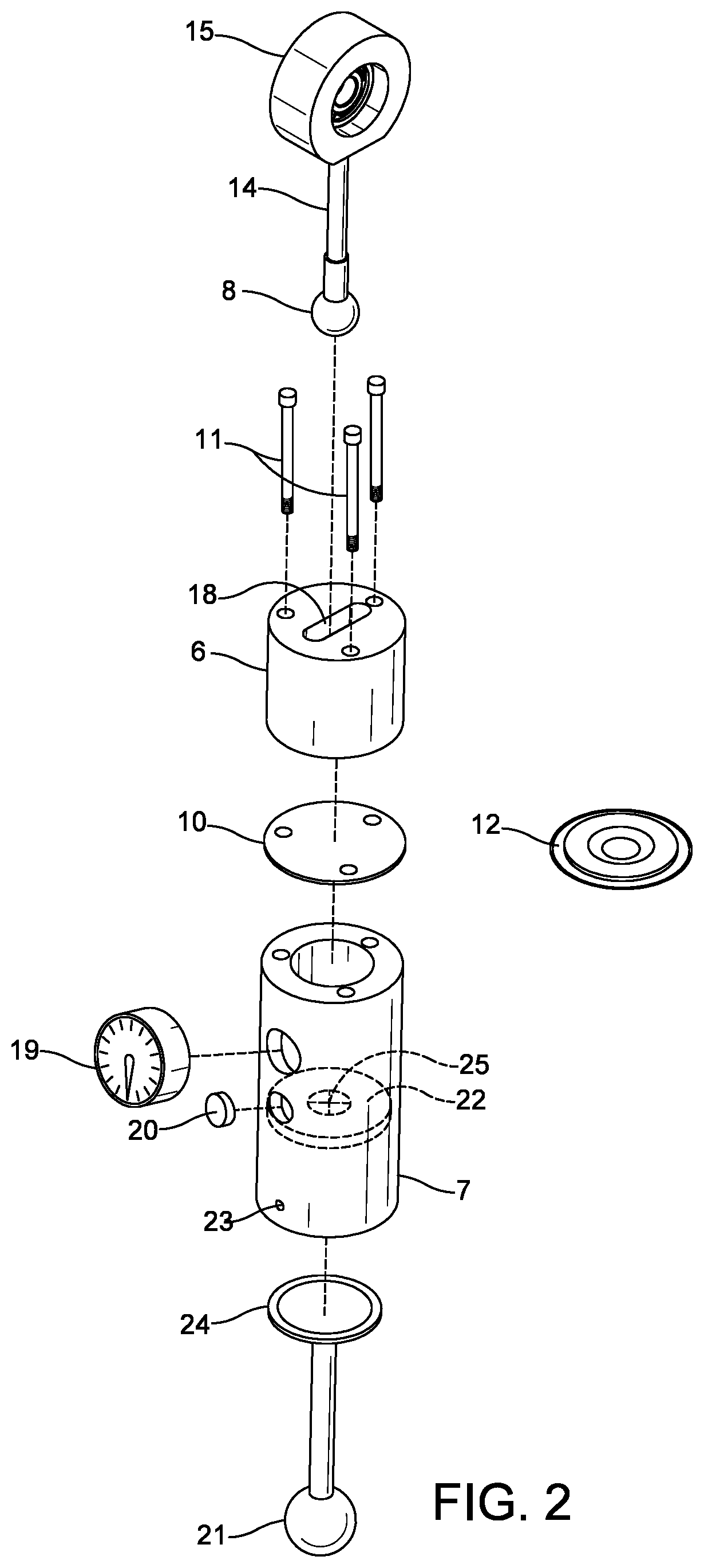
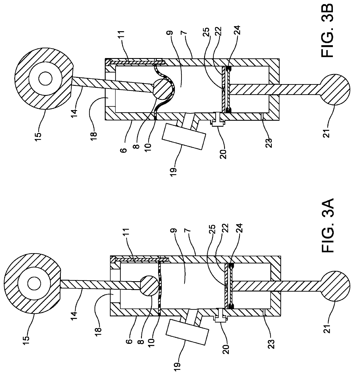
The invention is a new design for a drum pedal that uses a flat diaphragm with a spherical piston to improve reliability and reduce friction. The flat diaphragm allows for elastic deformation, which eliminates the need for a convolute and failure modes experienced with other designs. The use of a single connecting rod between the pedal and piston reduces complexity and friction. Additionally, the inventor has developed a solution for adjusting the feel and return speed of the drum pedal by making the cam shape of the track hub adjustable, and a new solution for preventing slack in the flexible chain or strap that connects the footboard to the track hub or hi-hat stand. The solution is a flat, straight, stiff piece of material that can be easily attached to the flexible connector and eliminates any slack that can alter the feel and playability of the pedal.

Problems solved by technology

These constraints contribute to the failure of the rolling diaphragm, because the rolling diaphragm's radius must be small, and the work performed each time during inversion through the convolute is substantial.
This bouncy feel is unique and desirable for playability, and has not previously been possible to implement with spring technology or a pneumatic setup using a rolling diaphragm.
In addition, the uniformly flat shape of the diaphragm makes the exact location of the piston's resting place on the diaphragm unimportant.

Method used


Image

  • Pneumatic return for foot pedals associated with percussion instruments
  • Pneumatic return for foot pedals associated with percussion instruments
  • Pneumatic return for foot pedals associated with percussion instruments

Examples


embodiment 41

[0050]An exemplary embodiment of the stiffener, shown in FIG. 8, consists of a rigid C-channel member 41, with multiple pairs of claws 42 that protrude from and reach around the long open edges of the C-channel member 41 and grab the edges of the chain links 4 around the outside. This claw embodiment 41 of the stiffener is configured to be snapped onto the chain 4, and covers a length of the chain 4 on three sides.

embodiment 43

[0051]A second exemplary embodiment of the stiffener, shown in FIG. 9, consists of a rigid C-channel member 43, with multiple pairs of reverse claws 44 that protrude from the central backbone portion of the C-channel member 43 through a plurality of the chain links 4. This reverse claw embodiment 43 of the stiffener is configured to be snapped onto the chain 4, and covers a length of the chain 4 on three sides.

embodiment 46

[0052]A third exemplary embodiment of the stiffener, shown in FIG. 10, is configured to be used with a flexible strap 45, rather than a chain, and consists of a length of flat stock 46 with multiple clips 47 protruding outwards. This clip embodiment 46 of the stiffener is configured to be clipped onto the strap 45, and covers the strap 45 on one edge.

[0053]Each of the stiffener embodiments may be easily attached to or detached from the chain 4 or strap 45 of a drum pedal or hi-hat stand, so as to switch between a flexible and non-flexible playing configuration.

[0054]It will therefore be appreciated that the above-described invention provides multiple adjustments, both mechanical and pneumatic, which enable a user to customize or fine-tune the drum pedal assembly to a degree heretofore unattainable in conventional pedal return mechanisms.


PUM


Abstract

This improvement to a pneumatic return mechanism for percussion foot pedals incorporates a flat or bowl-shaped diaphragm rather than a rolling diaphragm, and a piston which is spherical rather than cylindrical, producing a bouncy feel for the player. A further improvement to the track hub of a percussion foot pedal enables bump fasteners to be removably inserted, to add lift and alter beater acceleration. A further improvement is a removable stiffener which prevents slack in the connector between the footboard and track hub of the percussion foot pedal, which may occur during fast drumming.

Description

BACKGROUND OF THE INVENTION[0001]The inventor received U.S. Pat. No. 4,945,802 in 1990 for a “Pneumatic Return for Foot Pedals Associated with Percussion Instruments” (the “1990 invention.”) The 1990 invention is an alternative return mechanism for bass drum pedals and hi-hat stand pedals, which uses a pneumatic device to return the footboard of the pedal and connected drum beater or cymbal to a neutral position after each strike, instead of a traditional spring mechanism.[0002]Springs had been and continue to be widely used for this purpose, though they have problems. For example, coil springs tend to lose their elasticity over time. They also tend to be noisy, are not easily calibrated, and fail over time. In order to obtain a different feel, for example with regard to movement, resistance to movement, beater bar speed, or timing, one must usually purchase an entire new pedal assembly. Substitution of different size springs, where possible, can be a time-consuming chore.[0003]The ...

Claims


Application Information

Patent Timeline
Patent Type & Authority Patents(United States)
IPC IPC(8): G10D13/11
CPCG10D13/11G10D13/02
Inventor RUPRECHT, DAVID S
Owner RUPRECHT DAVID S
Learn More