Calibration method for current detection and protection mechanism and calibration device using same

a protection mechanism and current detection technology, applied in the direction of instruments, safety/protection circuits, transportation and packaging, etc., can solve the problems of large conversion errors of usb-c control chips, analog-to-digital conversion resolution of control chips, and disadvantages of low-level control chips

Active Publication Date: 2022-09-27
PRIMAX ELECTRONICS LTD
View PDF4 Cites 0 Cited by
  • Summary
  • Abstract
  • Description
  • Claims
  • Application Information

AI Technical Summary

Problems solved by technology

However, the use of the low-level control chip usually has some drawbacks.
For example, since the capability of the control chip to withstand noise is weak or the analog-to-digital conversion resolution of the control chip is poor, the USB-C control chip is prone to large conversion errors during the process of converting the analog transmission current into the analog-to-digital conversion value.
Consequently, the generated analog-to-digital conversion value is suffer

Method used


Image

  • Calibration method for current detection and protection mechanism and calibration device using same
  • Calibration method for current detection and protection mechanism and calibration device using same
  • Calibration method for current detection and protection mechanism and calibration device using same

Examples


first embodiment

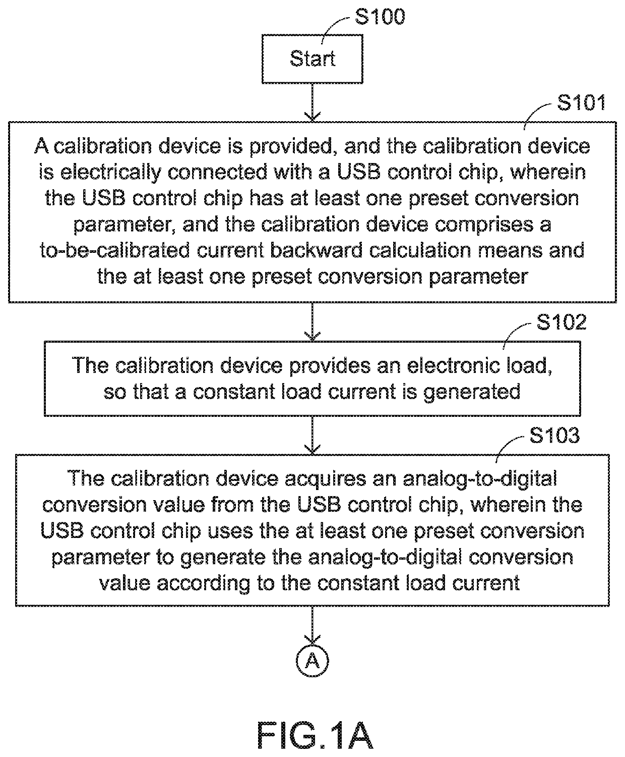
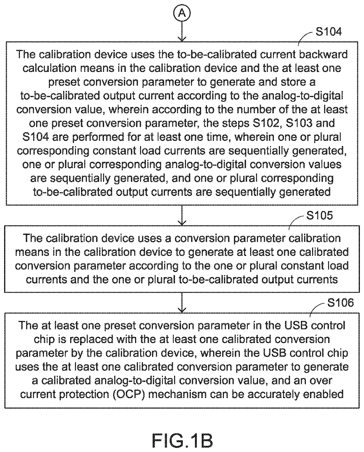
[0038]The present invention provides a calibration method for a current detection and protection mechanism. FIGS. 1A and 1B are a flowchart of a calibration method for a current detection and protection mechanism according to the present invention. The calibration method at least comprises the following steps.

[0039]In a step S100, the calibration method is started.

[0040]In a step S101, a calibration device is provided, and the calibration device is electrically connected with a USB control chip. The USB control chip has at least one preset conversion parameter. The calibration device comprises a to-be-calibrated current backward calculation means and the at least one preset conversion parameter.

[0041]In an embodiment, the USB control chip is installed in an electronic product or an under-test circuit board. Moreover, the electronic product or the under-test circuit board is electrically connected with the calibration device. For example, the electronic product is a docking station. ...

second embodiment

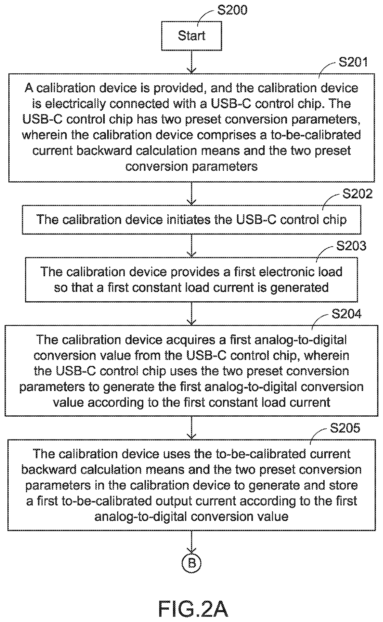
[0060]FIGS. 2A-2B and 2C illustrate a flowchart of a calibration method for a current detection and protection mechanism according to the present invention. The calibration method at least comprises the following steps.

[0061]In a step S200, the calibration method is started.

[0062]In a step S201, a calibration device is provided, and the calibration device is electrically connected with a USB-C control chip. The USB-C control chip has two preset conversion parameters. The calibration device comprises a to-be-calibrated current backward calculation means and the two preset conversion parameters.

[0063]In an embodiment, the USB-C control chip is installed in an electronic product or an under-test circuit board. Moreover, the electronic product or the under-test circuit board is electrically connected with the calibration device. For example, the electronic product is a docking station. It is noted that the example of the electronic product is not restricted.

[0064]Moreover, the electroni...


PUM


Abstract

A calibration device includes a main control unit, an interface conversion unit and an electronic load generation unit. The electronic load generation unit provides an electronic load, so that a USB control chip generates a constant load current. The USB control chip uses at least one preset conversion parameter to generate an analog-to-digital conversion value according to the constant load current. The main control unit generates a to-be-calibrated output current according to the analog-to-digital conversion value. The main control unit generates at least one calibrated conversion parameter according to the constant load current and the to-be-calibrated output current. The USB control chip uses the at least one calibrated conversion parameter to generate a calibrated analog-to-digital conversion value, so that an over current protection mechanism is accurately enabled.

Description

FIELD OF THE INVENTION[0001]The present invention relates to a calibration method for a current detection and protection mechanism and a calibration device using the calibration method, and more particularly to a calibration method for a current detection and protection mechanism of a universal serial bus (USB) control chip and a calibration device using the calibration method.BACKGROUND OF THE INVENTION[0002]The universal serial bus (USB) transfer specification has been an interface transmission standard that is widely adopted by various electronic devices. In particular, the Type C universal serial bus (USB-C) transfer specification has become popular in recent years. On the basis of the USB standard, the USB-C transfer specification provides the higher power transfer capacity and the faster data transfer speed in order to meet the increasing needs of achieving the connection between modern electronic devices.[0003]The USB-C transfer specification has a Power Delivery (PD) functio...

Claims


Application Information

Patent Timeline
IPC IPC(8): G06F3/00G06F13/38G06F13/40G06F13/42H02J7/00G06F1/3215
CPCG06F13/387G06F1/3215G06F13/4068G06F13/4282H02J7/0036H02J7/00304G06F2213/0042H02J2207/30
Inventor YANG, SHUN-FUCHEN, WEI-CHENGLI, JEN-CHENGCHAN, WEN-HSIENFANG, PO-YAO
Owner PRIMAX ELECTRONICS LTD
Why Eureka
Try Eureka