Electric transmission device in relatively rotating parts

a technology of electric transmission device and rotating part, which is applied in the direction of inductance, magnetic circuit shape/form/construction, artificial legs, etc., can solve the problems of chipping of the core of the magnetic element or peeling of the coating of the wire of the coil

Active Publication Date: 2022-09-27
NTN CORP
View PDF19 Cites 0 Cited by
  • Summary
  • Abstract
  • Description
  • Claims
  • Application Information

AI Technical Summary

Benefits of technology

[0010]Each of the above electric transmission devices based on magnetic coupling, without a cable, eliminates the risk of breaking of wire, ensures a wide movable range, minimizes abrasion. Nevertheless, the two magnetic elements can come into contact with each other during assembling or during operation, whereby there is a possibility that the core of the magnetic element will become chipped or a coating of a wire of the coil will be peeled. Each magnetic element is supported by a housing or a shaft via a bearing, and thus hardly moves in the radial direction. Therefore, the magnetic elements would hardly come into contact with each other due to movement thereof in the radial direction. However, the magnetic elements can move in the axial direction to come into contact with each other.
[0011]An object of the present invention is to provide an electric transmission device that is provided at relatively rotating parts of a mechanical apparatus and that is able to stabilize magnetic characteristics, is able to avoid damage to two magnetic elements caused by contact therebetween, and further has good assemblability.

Problems solved by technology

Nevertheless, the two magnetic elements can come into contact with each other during assembling or during operation, whereby there is a possibility that the core of the magnetic element will become chipped or a coating of a wire of the coil will be peeled.

Method used


Image

  • Electric transmission device in relatively rotating parts
  • Electric transmission device in relatively rotating parts
  • Electric transmission device in relatively rotating parts

Examples


first embodiment

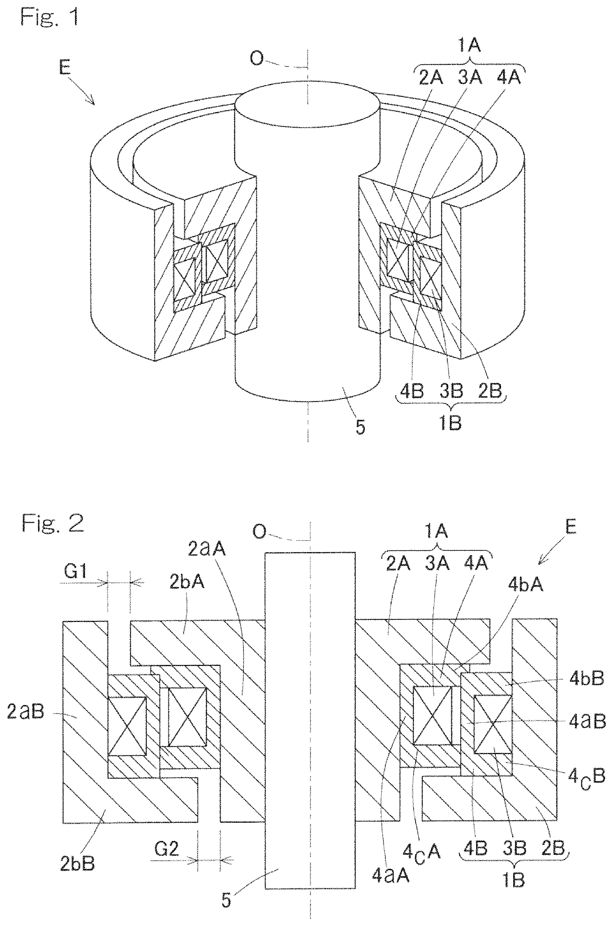
[0052]An embodiment of the present invention will be described with reference to FIG. 1 to FIG. 3. FIG. 1 is a partially cutaway perspective view of an electric transmission device in which the electric transmission device is assembled to a shaft. FIG. 2 is a longitudinal sectional view of the electric transmission device. The electric transmission device E is configured to be provided at relatively rotating parts of a mechanical apparatus such as a later-described assist suit. The electric transmission device E is related to a transformer. The device includes a pair of first and second magnetic elements 1A and 1B capable of rotating relative to each other about the same axis O. These first and second magnetic elements 1A and 1B each include a core 2A (2B), a coil 3A (3B), and a bobbin 4A (4B). The coils 3A and 3B of both magnetic elements 1A and 1B are located at the inner and outer sides in a radial direction, respectively, and are magnetically coupled to each other. The magnetic...

second embodiment

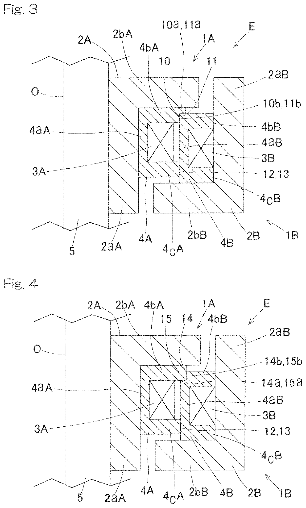
[0068]In the configuration of the electric transmission device shown in FIG. 4, in contrast to the configuration in FIG. 3, an annular cut 14 that is open outward in the axial direction and has a rectangular cross-sectional shape is provided on the inner circumferential surface of the flange portion 4bB of the second bobbin 4B. A corner portion 15 at the radially outer side of the flange portion 4bA of the first bobbin 4A is engaged with the annular cut 14. In this case, a surface 14a of the annular cut 14 that faces in the axial direction and a surface 15a of the corner portion 15 that faces in the axial direction function as the contact surfaces in the axial direction of the flange portions 4bB and 4bA, respectively. A surface 14b of the annular cut 14 that faces in the radial direction and a surface 15b of the corner portion 15 that faces in the radial direction function as the contact surfaces in the radial direction of the flange portions 4bB and 4bA, respectively.

third embodiment

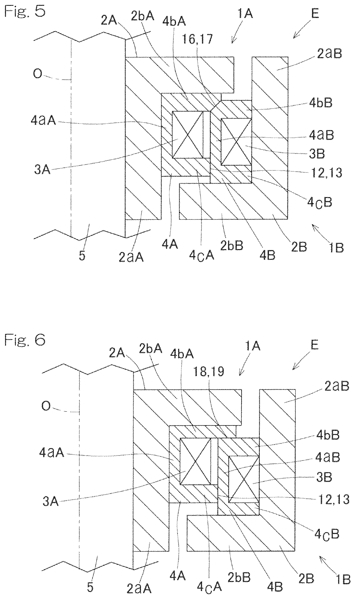
[0069]In the configuration of the electric transmission device shown in FIG. 5, inclined surfaces 16 and 17 that are inclined in the radial direction and are slidably in contact with each other are provided on the outer circumferential surface of the flange portion 4bA of the first bobbin 4A and the inner circumferential surface of the flange portion 4bB of the second bobbin 4B, respectively. In this case, the inclined surfaces 16 and 17 function as the contact surfaces in the axial direction of the flange portions 4bA and 4bB, respectively. The inclined surfaces 16 and 17 also function as the contact surfaces in the radial direction of the flange portions 4bA and 4bB, respectively.


PUM

PropertyMeasurementUnit
magneticaaaaaaaaaa
conductiveaaaaaaaaaa
diameteraaaaaaaaaa

Abstract

Provided is an electric transmission device that is provided at relatively rotating parts of a mechanical apparatus. The electric transmission device (E) includes a pair of magnetic elements (1A, 1B) relatively rotatable about the same axis (O). The magnetic elements (1A, 1B) each includes a core (2A, 2B) and a coil (3A, 3B) having a conductive wire. One of the coil (3A) and the coil (3B) is located at an inner side of the other coil in a radial direction, and the coils (3A and 3B) are magnetically coupled to each other. Each bobbin (4A, 4B) includes a cylinder (4aA, 4aB) and a dis-shaped flange (4bA, 4bB). The flanges (4bA, 4bB) are slidably in contact with each other at contact surfaces (10a, 11a) thereof in the axial direction.

Description

CROSS REFERENCE TO THE RELATED APPLICATION[0001]This application is a continuation application, under 35 U.S.C. § 111(a), of international application No. PCT / JP2017 / 017136, filed May 1, 2017, which claims based on and claims Convention priority to Japanese patent application No. 2016-095206, filed May 11, 2016, and Japanese patent application No. 2016-218804, filed Nov. 9, 2016, the entire disclosures of which are herein incorporated by reference as a part of this application.BACKGROUND OF THE INVENTIONField of the Invention[0002]The present invention relates to an electric transmission device in relatively rotating parts, the electric transmission device being disposed at the relatively rotating parts in a robot, an assist suit, or another mechanical apparatus having the relatively rotating parts such as a joint. The electric transmission device is configured to transmit electric power or a signal in a non-contact manner.Description of Related Art[0003]A joint or rotating parts in...

Claims


Application Information

Patent Timeline
Patent Type & Authority Patents(United States)
IPC IPC(8): H01F38/14A61F2/60H01F38/18A61F2/54H02K1/28A61H3/00
CPCH01F38/14A61F2/54A61F2/60A61H3/00H01F38/18H02K1/28A61H2201/1215A61H2201/164A61H2201/165A61H2201/1635
Inventor SAKAI, KAYOSHIMAZU, EIICHIROUKANBE, SHOUGO
Owner NTN CORP
Why Eureka
Try Eureka