Continuous cable winch

Active Publication Date: 2022-11-08
DUALELEVATOR
View PDF16 Cites 0 Cited by
  • Summary
  • Abstract
  • Description
  • Claims
  • Application Information

AI Technical Summary

Benefits of technology

[0016]When an undervoltage is detected by the means for voltage detection and / or an overcurrent is detected by the means for current detection, the control unit of the continuous cable winch is further preferably designed to change the rotation speed of the AC motor depending on the detected undervoltage and / or the detected overcurrent such that the electrical power requirement of the AC motor drops by the same amount as the AC voltage, which is provided by the power supply system, across the frequency converter. To this end, the control unit compares, for example, the detected current or the detected voltage with preprogrammed setpoint values and, in the event of a deviation, the motor is switched over to a corresponding stage such that electrical and mechanical torque are of substantially equal magnitude. This prevents, in particular, passage of the continuous cable winch and / or overcurrents in the AC motor.
[0017]According to a further preferred embodiment of the invention, the control unit of the continuous cable winch is designed to halve and to double the electrical power requirement of the AC motor. Therefore, the AC motor is preferably actuated in stages which are multiples of one another. It is particularly advantageous here that this can be realized in a simple manner, for example, by resistance bridge circuits or simple switching processes, so that excessively complex actuation is avoided, as would be the case, for example, in the event of continuous actuation of an AC motor.
[0019]According to a particularly preferred embodiment, the frequency converter and the control unit of the continuous cable winch are in the form of an integrated apparatus. A particular advantage of an integrated, in particular integral, design is the resulting modular construction which allows simple retrofitting to existing AC motors of continuous cable winches.
[0021]According to a further preferred embodiment of the invention, the AC motor of the continuous cable winch is designed for operation with a single-phase rated AC voltage of 230 V. The AC motor is accordingly in the form of a 1-phase 230 V AC motor. The high replacement part density and the simple servicing of AC motors of this kind are particularly advantageous here. This is particularly important in countries with a poor infrastructure which usually also provide a significantly unstable power supply system.

Problems solved by technology

These superstructures of continuous cable winches usually have the disadvantage that voltage dips in the power supply system have a direct effect on the drive unit and the continuous cable winch can accordingly drop to an unstable operating point.
This operating behavior leads, in particular, to continuous cable winches being used only to a limited extent in countries with a poor electricity supply.

Method used


Image

  • Continuous cable winch
  • Continuous cable winch
  • Continuous cable winch

Examples


Embodiment Construction

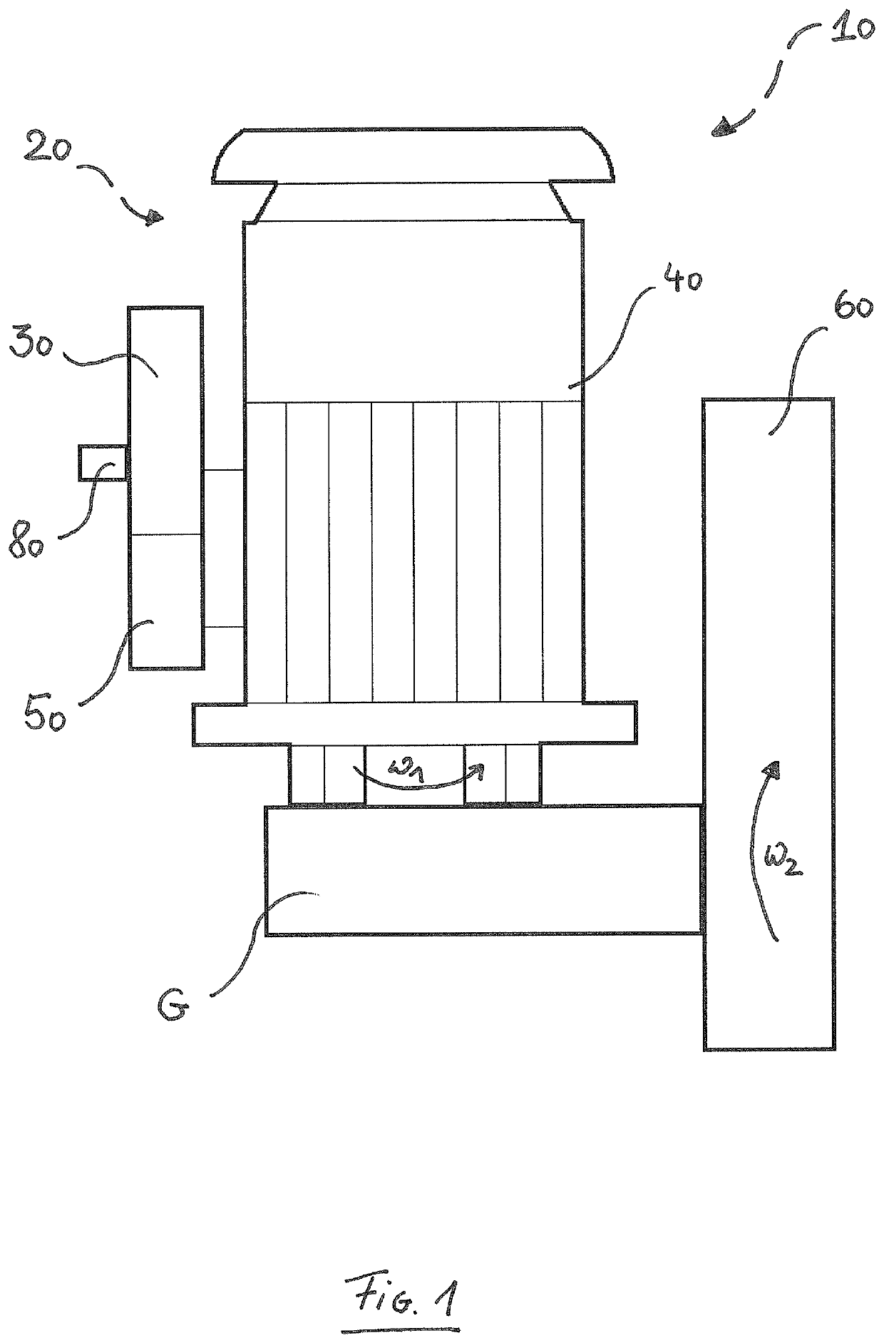
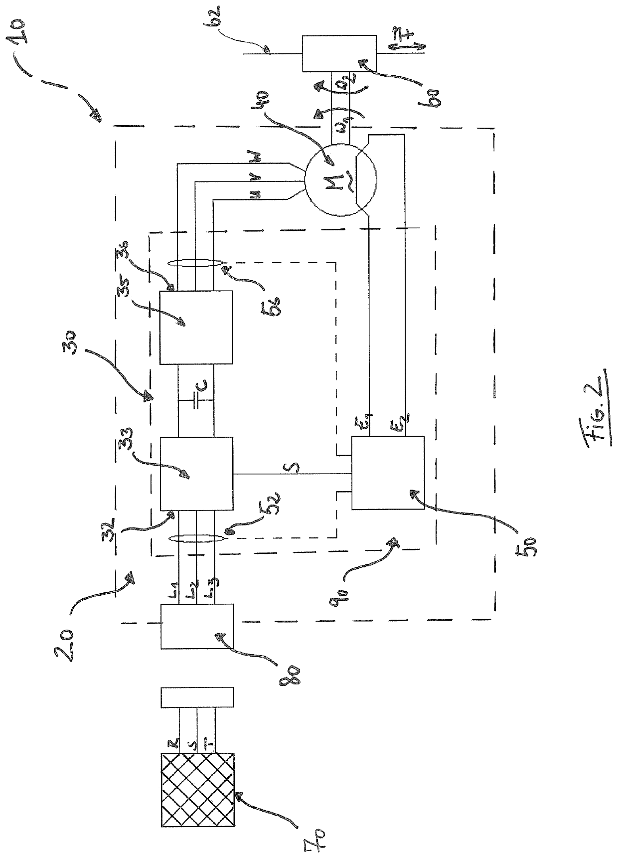
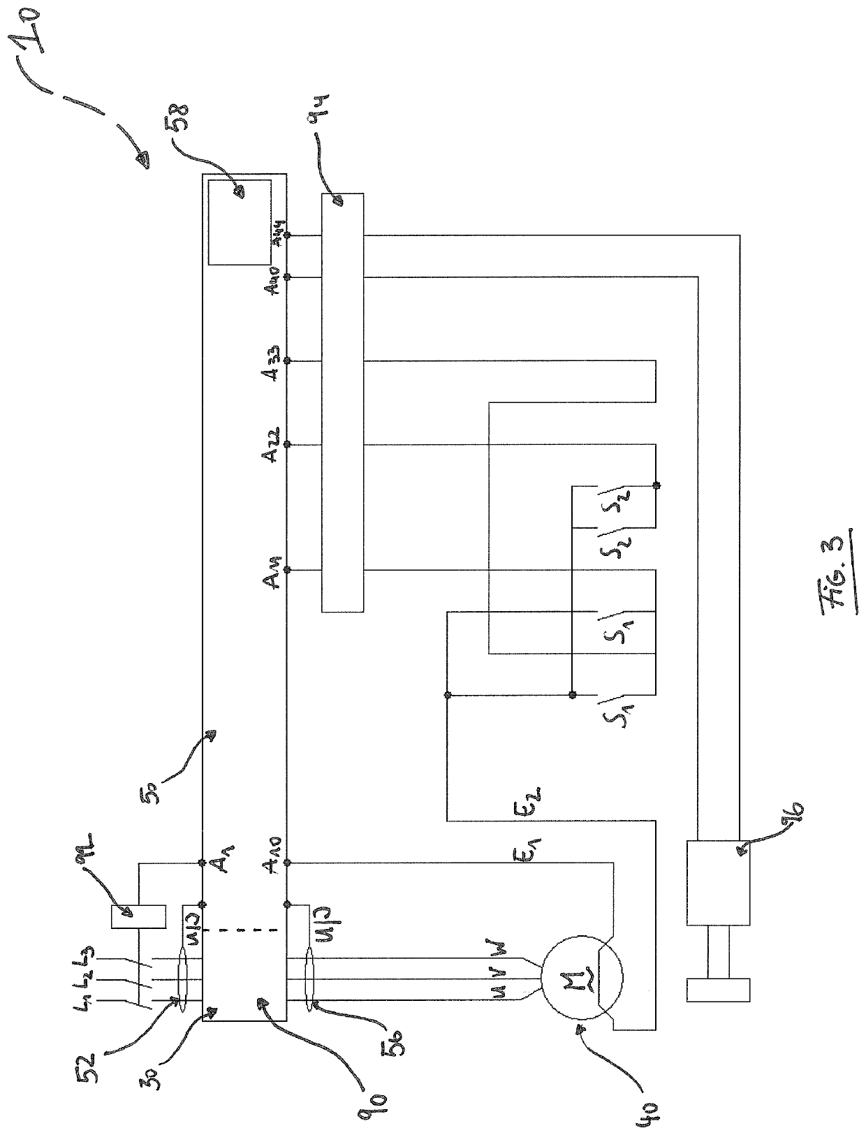
[0033]FIG. 1 shows a continuous cable winch comprising a drive unit 20, wherein the drive unit 20 comprises a frequency converter 30 with a primary side for drawing current from a power supply system and with a secondary side for outputting an AC voltage, an AC motor 40 for driving the continuous cable winch 10 at a variable rotation speed ω1, which AC motor is supplied with the AC voltage by the frequency converter 30, a control unit 50 which is interconnected with the frequency converter 30 and the AC motor 40 for the purpose of controlling the drive unit 20, and an output unit 60 with a second rotation speed ω2 for applying a drive force to a cable (not illustrated), which output unit is coupled to the drive unit 20.

[0034]The output unit 60 with a variable rotation speed ω2 is coupled to the drive unit 20 by means of a connecting device G, for example by means of a transmission, so that these rotation speeds have a transmission ratio. In a further embodiment, the output unit 60 a...


PUM


Abstract

The invention relates to a continuous cable winch comprising a drive unit (20) and an output unit (60) for applying a drive force to a cable, which output unit is coupled to the drive unit (20).According to the invention, it is proposed that the drive unit (20) has a frequency converter (30) with a primary side (32) for drawing current from a power supply system (33) and a secondary side (36) for outputting an AC voltage (UU, UV, UW), an AC motor (40) for driving the continuous cable winch (10) at a variable rotation speed (ω1), which AC motor is supplied with the AC voltage (UU, UV, UW) by the frequency converter (30), a control unit (50) which is interconnected with the frequency converter (30) and the AC motor (40) for the purpose of controlling the drive unit (20), wherein the control unit (50) is designed to change the rotation speed (ω1) of the AC motor (40) by means of the frequency converter (30).

Description

RELATED APPLICATION (PRIORITY CLAIM)[0001]This application is a National Phase Under Section 371 of International Application No. PCT / EP2016 / 063747, filed Jun. 15, 2016.FIELD OF THE INVENTION[0002]The present invention relates to a continuous cable winch comprising a drive unit and an output unit for applying a drive force to a cable, which output unit is coupled to the drive unit.BACKGROUND OF THE INVENTION[0003]Winches in general have been known for a long time and are used to lift loads or people, in particular to bridge vertical differences, in all areas of industry. A specific type of winch is the so-called continuous cable winch in which the cable is guided through the winch instead of rolling on the winch, for example in a drum. The cable can hang down, for example, on one or both sides of the continuous cable winch due to the force of gravity or on account of a load acting on it, so that the continuous cable winch does not need to store that part of the cable which is guided...

Claims


Application Information

Patent Timeline
Patent Type & Authority Patents(United States)
IPC IPC(8): B66D1/46B66D1/48E04G3/32
CPCB66D1/46B66D1/485E04G3/32H02P7/00
Inventor LÜLFING, FRANK
Owner DUALELEVATOR
Why Eureka
Try Eureka