Wind power generation device
a power generation device and wind turbine technology, applied in the direction of machines/engines, mechanical equipment, mechanical circuit shapes/forms/construction, etc., to achieve the effect of improving problems
- Summary
- Abstract
- Description
- Claims
- Application Information
AI Technical Summary
Benefits of technology
Problems solved by technology
Method used
Image
Examples
first embodiment
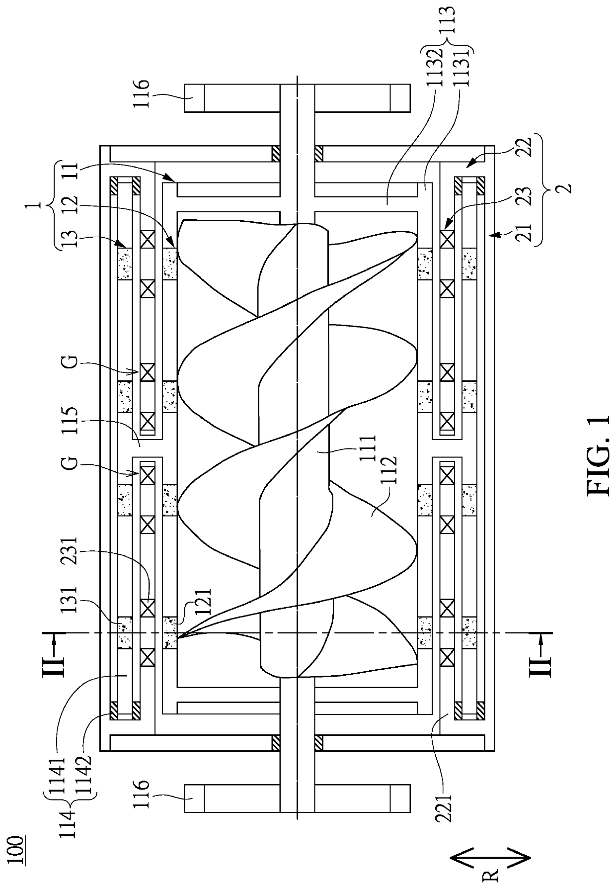
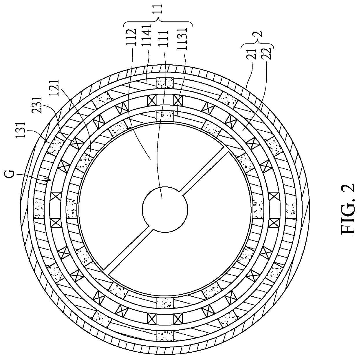
[0022]Referring to FIG. 1 and FIG. 2, a first embodiment of the present disclosure provides a wind power generation device 100, which includes a rotor assembly 1 and a stator assembly 2 arranged outside of the rotator assembly 1. The rotator assembly 1 includes a rotating member 11, a first magnetic module 12 disposed on the rotating member 11, and a second magnetic module 13 disposed on the rotating member 11 and arranged outside of the first magnetic module 12.
[0023]The rotating member 11 has a column 111, a spiral blade 112 connected to an outer surface of the column 111, a first carrier 113 fixed to the column 111, a second carrier 114 arranged outside of the first carrier 113, a connecting member 115 connecting the first carrier 113 and the second carrier 114, and two wind guides 116 respectively fixed to two opposite ends of the column 111.
[0024]Moreover, the spiral blade 112 has a length along a central axis of the column 111, and the length is greater than 0.5 pitch of the s...
second embodiment
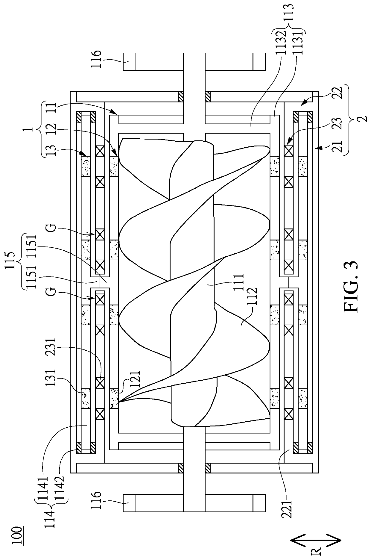
[0040]Referring to FIG. 3, a second embodiment of the present disclosure is similar to the first embodiment of the present disclosure, so that descriptions of the same components in the first and second embodiments of the present disclosure will be omitted for the sake of brevity, the main difference between the first and second embodiments being the rotating member 11.
[0041]Specifically, the connecting member 115 of the rotating member 11 in the present embodiment includes two gears 1151 meshingly engaged with each other, and the two gears 1151 are respectively fixed to the inner hollow cylinder 1131 and the outer hollow cylinder 1141. When the spiral blade 112 drives the first carrier 113 to rotate, the first carrier 113 synchronously rotates the outer hollow cylinder 1141 (i.e., the first carrier 113 and the outer hollow cylinder 1141 are rotated at the same speed) through the cooperation of the two gears 1151.
third embodiment
[0042]Referring to FIG. 4, a third embodiment of the present disclosure is similar to the first embodiment of the present disclosure, so that descriptions of the same components in the first and third embodiments of the present disclosure will be omitted for the sake of brevity, the main difference between the first and third embodiments being the rotating member 11.
[0043]Specifically, the rotating member 11 of the present embodiment excludes the connecting member 115, and the inner hollow cylinder 1131 and the outer hollow cylinder 1141 are separated from each other. When the spiral blade 112 drives the first carrier 113 to rotate, the first carrier 113 synchronously rotates the outer hollow cylinder 1141 (i.e., the first carrier 113 and the outer hollow cylinder 1141 are rotated at the same speed) only by using the first magnetic module 12 to magnetically connect to the second magnetic module 13.
PUM
 Abstract
Description
Claims
Application Information
 - R&D
- Intellectual Property
- Life Sciences
- Materials
- Tech Scout
- Unparalleled Data Quality
- Higher Quality Content
- 60% Fewer Hallucinations
Browse by: Latest US Patents, China's latest patents, Technical Efficacy Thesaurus, Application Domain, Technology Topic, Popular Technical Reports.
© 2025 PatSnap. All rights reserved.Legal|Privacy policy|Modern Slavery Act Transparency Statement|Sitemap|About US| Contact US: help@patsnap.com


